EP0158139A1 - Fehlerkorrigierte Korpuskularstrahl-Lithographie - Google Patents
Fehlerkorrigierte Korpuskularstrahl-Lithographie Download PDFInfo
- Publication number
- EP0158139A1 EP0158139A1 EP85102832A EP85102832A EP0158139A1 EP 0158139 A1 EP0158139 A1 EP 0158139A1 EP 85102832 A EP85102832 A EP 85102832A EP 85102832 A EP85102832 A EP 85102832A EP 0158139 A1 EP0158139 A1 EP 0158139A1
- Authority
- EP
- European Patent Office
- Prior art keywords
- mask
- diaphragm
- corpuscular
- errors
- pinhole diaphragm
- Prior art date
- Legal status (The legal status is an assumption and is not a legal conclusion. Google has not performed a legal analysis and makes no representation as to the accuracy of the status listed.)
- Granted
Links
Images


Classifications
-
- H—ELECTRICITY
- H01—ELECTRIC ELEMENTS
- H01J—ELECTRIC DISCHARGE TUBES OR DISCHARGE LAMPS
- H01J37/00—Discharge tubes with provision for introducing objects or material to be exposed to the discharge, e.g. for the purpose of examination or processing thereof
- H01J37/30—Electron-beam or ion-beam tubes for localised treatment of objects
- H01J37/317—Electron-beam or ion-beam tubes for localised treatment of objects for changing properties of the objects or for applying thin layers thereon, e.g. for ion implantation
- H01J37/3174—Particle-beam lithography, e.g. electron beam lithography
-
- B—PERFORMING OPERATIONS; TRANSPORTING
- B82—NANOTECHNOLOGY
- B82Y—SPECIFIC USES OR APPLICATIONS OF NANOSTRUCTURES; MEASUREMENT OR ANALYSIS OF NANOSTRUCTURES; MANUFACTURE OR TREATMENT OF NANOSTRUCTURES
- B82Y10/00—Nanotechnology for information processing, storage or transmission, e.g. quantum computing or single electron logic
-
- B—PERFORMING OPERATIONS; TRANSPORTING
- B82—NANOTECHNOLOGY
- B82Y—SPECIFIC USES OR APPLICATIONS OF NANOSTRUCTURES; MEASUREMENT OR ANALYSIS OF NANOSTRUCTURES; MANUFACTURE OR TREATMENT OF NANOSTRUCTURES
- B82Y40/00—Manufacture or treatment of nanostructures
-
- H—ELECTRICITY
- H01—ELECTRIC ELEMENTS
- H01J—ELECTRIC DISCHARGE TUBES OR DISCHARGE LAMPS
- H01J37/00—Discharge tubes with provision for introducing objects or material to be exposed to the discharge, e.g. for the purpose of examination or processing thereof
- H01J37/30—Electron-beam or ion-beam tubes for localised treatment of objects
- H01J37/304—Controlling tubes by information coming from the objects or from the beam, e.g. correction signals
-
- H—ELECTRICITY
- H01—ELECTRIC ELEMENTS
- H01J—ELECTRIC DISCHARGE TUBES OR DISCHARGE LAMPS
- H01J2237/00—Discharge tubes exposing object to beam, e.g. for analysis treatment, etching, imaging
- H01J2237/30—Electron or ion beam tubes for processing objects
- H01J2237/304—Controlling tubes
- H01J2237/30455—Correction during exposure
-
- H—ELECTRICITY
- H01—ELECTRIC ELEMENTS
- H01J—ELECTRIC DISCHARGE TUBES OR DISCHARGE LAMPS
- H01J2237/00—Discharge tubes exposing object to beam, e.g. for analysis treatment, etching, imaging
- H01J2237/30—Electron or ion beam tubes for processing objects
- H01J2237/317—Processing objects on a microscale
- H01J2237/3175—Lithography
- H01J2237/31793—Problems associated with lithography
- H01J2237/31794—Problems associated with lithography affecting masks
-
- H—ELECTRICITY
- H01—ELECTRIC ELEMENTS
- H01J—ELECTRIC DISCHARGE TUBES OR DISCHARGE LAMPS
- H01J2237/00—Discharge tubes exposing object to beam, e.g. for analysis treatment, etching, imaging
- H01J2237/30—Electron or ion beam tubes for processing objects
- H01J2237/317—Processing objects on a microscale
- H01J2237/3175—Lithography
- H01J2237/31793—Problems associated with lithography
- H01J2237/31798—Problems associated with lithography detecting pattern defects
Definitions
- the invention relates to an apparatus for detecting errors in exposure masks for corpuscular beam lithography and to methods of generating error-corrected mask images in corpuscular beam lithographic systems.
- proximity printers wherein a transmission mask is imaged by a wide diameter electron beam at a 1:1 scale on a substrate covered with an electron-sensitive layer.
- Such arrangements afford a high throughput and thus an inexpensive production process. Details of the related processes are described, for instance, in the article "Electron-beam proximity printing - a new high-speed lithography method for submicron structures" by H. Bohlen et al. in IBM J. Res. Devel., Vol. 26, No. 5, September 1982, p. 568 et seq. That method provides for the substrate to be shifted in steps, generating in each case a mask shadow projection image corresponding, for example, to a complete semiconductor chip. Mask errors, impairing the operation of the semiconductor circuit, may lead to the entire exposed substrate becoming unusable.
- Mask distortions may occur, for example, if the mask is unduly heated during its manufacture or by the incident beam. Errors of the imaging system affect, for instance,-in an uncontrollable manner the inclination of the parallel beam incident on the mask, thus leading to displacements in the shadow image. Causes of such errors may be insufficiently homogeneous magnetic fields or changes in the magnetic field by induced eddy currents occurring when a relatively thin electron beam is made to rapidly raster-scan the mask for its full illumination.
- the probes used must be extremely fine, in order to reach the desired resolution.
- fine probes for example, a strongly focussed electron beam, the local thermal load on the tested mask increases, or the measuring signal available is extremely low and subject to much noise.
- the transmission masks necessary for shadow projection corpuscular beam lithgraphy represent the mask pattern as physical apertures (hole pattern), as no material is known that is completely transparent to corpuscular beams.
- Such masks are particularly sensitive to impurity particles which even in hyperpure rooms settle on the mask, thus drastically reducing the yield of very large scale integrated circuits.
- Protecting a mask against impurity particles by protective foils, as is done in optical photolithography, is, therefore, ineffective with, corpuscular beams.
- the mask is impinged upon by the same electron beam as is used for shadow projection lithography.
- the shadow projection pattern generated by the mask is scanned through at least one pinhole diaphragm having an aperture with a diameter of typically 0.5 ⁇ m and which is displaced relative to the mask; relative displacement with a high spatial resolution can be achieved by altering the inclination of the electron beam.
- Highly responsive detectors are arranged behind the diaphram apertures to generate from the low electron current a measuring signal with an adequate signal-to-noise ratio. If a single diaphragm is used, the detector consists of a scintillator which is followed by a secondary electron multiplier.
- the mask geometry can be extremely accurately determined at selected points; the obtainable resolution is about 25 nm. If the electron beam is tilted in two dimensions, it is possible to image by the single hole diaphragm also small mask sections on a point-by-point basis, thus generating, similar to a scanning electron microscope, although in transmission, an image of the respective mask section.
- the single hole diaphragm, together with the detector, is fixed on the X-Y table carrying the substrate (the semiconductor wafer) during exposure. Suitable portions of the mask structures, representing the pattern to be exposed, are used as measuring structures.- These mask portions or points, which may be arbitrarily selected, are then positioned below the pinhole diaphragm by displacing the table and, if necessary, accurately aligned, using the above-described two-dimensional imaging process. With the mask being fixed, the angle of inclination of the electron beam is subsequently altered, thus guiding the shadow projection image of the selected mask point across the pinhole diaphragm.
- the accurate position of the selected mask element may be derived from the relative position of the measuring signal with respect to the saw-tooth voltage used for beam tilting, taking into account the displacement of the detector from one measuring point to another which is very accurately interferometrically measured.
- correction signals which, during mask exposure, may be used to momentarily alter the angle of inclination of the electron beam, may be derived from those measuring results.
- the corrections also cover inevitable errors in the lithographic system.
- the very small pinhole diaphragm required by the high resolution would make the scanning of the entire mask (with a surface measuring up to some cm2) very time- consuming.
- the entire mask has to be scanned.
- the invention avoids this time problem by using a multihole diaphragm, whose apertures are arranged in matrix fashion and have a typical size of 0.5 pm.
- This diaphragm is integrated with a multiple element of the charge transfer type circuit that serves as a particle detector such that each aperture in the mask constitutes a window transmitting electrons to the electron detector arranged underneath it.
- This detector arrangement for electrons is guided in steps across the shadow image of the mask, being illuminated at each position at different angles of inclination of the electron beam.
- the electrons transversing the apertures are collected in the underlying semiconductor circuit and are serially read out for evaluation.
- the image of the mask is formed from the totality of the images thus recorded and compared with an electronically stored ideal pattern, in order to detect, for.instance, impurities on the mask. In that case, the scanning time for the entire mask is of the order of minutes.
- the entire mask can be tested in the same system that is used for exposure, so that having been found free from errors and impurity particles, the mask can be directly exposed, without having to be removed from the vacuum system thus avoiding the possibility of further contamination.
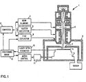
- Fig. 1 is a schematic of the layout of a known arrangement for electron beam lithography in which the present invention may be used.
- the electron beam column 1 comprises means for generating the electron beam 2, for its shaping and deflection; for that purpose, known electron sources, diaphragms, electron lenses, electrostatic and magnetic deflection systems are used.
- the electron beam 2 impinges upon a transmission mask 3 for generating a shadow image on the substrate 4, for example, a semiconductor wafer.
- the diameter of the electron beam 2 is preferably smaller than the diameter of the mask 3, so that for fully illuminating the mask, the latter is raster-scanned by the beam.
- Wafer 4 is generally larger than the mask 3, so that for its full exposure several individual exposures are required at different positions.
- the wafer is displaced by means of an X-Y table 5 and a controlled motor 11 connected thereto.
- the accurate position of the table is determined by a laser interferometer 10.
- the entire set-up is kept in a vacuum in housing 6.
- Data on the current position established by the laser interferometer 10 are fed through a circuit 13 for position measurement and a computer 12 connected thereto to a fine deflection control 9 of the electron beam which, for compensating for small positional errors, suitably corrects the inclination of the electron beam 2.
- a raster deflection means 8 for raster scanning the mask and beam blanking means 7 for interrupting the exposure step complete the lithographic system.
- Transmission masks of the kind to be employed for the described purpose consist, for example, of a very thin, tightly stretched semiconductor foil which is provided with a hole pattern in a dry etch step.
- the production process of such a mask is described, for example, in the article by Behringer et al. in IBM Technical Disclosure Bulletin, Vol. 26, No. 2, July 1983, page 690.
- Fig. 2 shows a first embodiment of the invention in the form of a single hole diaphragm for accurately determining the geometrical shape of the mask 3 by means of selected mask positions.
- a diaphragm 20 having a single, very small hole of typically 0.5 ⁇ m (diameter or lateral length), is provided on the X-Y table 5 outside the support area of wafer 4.
- Such a mask may be lithographically defined and be produced by dry etching.
- a scintillator 21 is positioned below the single hole diaphragm 20, in which the impinging electrons of beam 2 produce light flashes. These light flashes are fed at the mirrored edges of the scintillator 21 or by total reflection to the photosenstive surface of a secondary electron multiplier (photomultiplier) 22, in which electrons are highly amplified to result in an electronic output signal which may be fed through line 23 to suitable amplifier and evaluator circuits (not shown ⁇ .
- photomultiplier secondary electron multiplier
- the measuring process for determining the geometrical shape of the mask 3, for example, for determining mask distortions proceeds as follows. On mask 3 a number of points are selected and their ideal position is determined. These mask points may be related to structures already present on the mask, such as apertures with a lateral length of 1 x 1 ⁇ m or horizontal or vertical lines with widths of about 1 wm. Special measuring marks, which are introduced into the mask only for that purpose, are not necessary in this case, but may be used. For determining the geometrical shape of the masks twenty such points distributed across its entire surface are sufficient. At the beginning of measuring, the single hole diaphragm 20 is positioned and locked underneath one of the selected points by means of the X-Y table. According to Fig.
- the electron beam 2 is subsequently tilted into two extreme positions 2a and 2b, thus generating below the selected aperture 31 in mask 3 a partial beam moving across the small aperture 32 of the single hole diaphragm 20.
- the distance between the two extreme positions 30a, 30b of the partial beam is approx. 4 ⁇ m.
- the selected pattern element say, the aperture 31 of the mask 3
- photomultiplier 22 emits an output signal 36 which is symmetrical to the deflection voltage 35 for tilting the electron beam 2; in other words, the symmetry point S of the deflection corresponds to the voltage level for 0 deflection (perpendicular incidence) in an electrostatic deflection system, for example.
- Fig. 3B there is, according to Fig. 3B, a larger or less larerer displacement of the detector signal 36 with respect to the symmetry point S of the saw-tooth curve 35 for beam inclination.
- the single hole diaphragm 20 by displacing the X-Y table, is moved to the next selected point below the mask, where the same measurement is repeated. From the interferometrically measured displacement between the two points and the two measuring signals of the photomultiplier, the relative spacing of these two points can be very accurately determined. The relative spacings of all other selected mask points are similarly determined. For accurate position determination at each mask point, it is also possible to perform two beam inclinations in planes perpendicular to each other.
- the above-described measuring process may also be effected by means of a scanning electron beam, as is used for the actual exposure of wafer 4 through mask 3.
- a scanning electron beam electron beams with a diameter of about 1 mm are typically used, which in 1 msec., are guided in raster fashion along a strip across the mask length of about 10 mm.
- each 1 ⁇ m pattern element of the mask selected for accurate position measurement is illuminated by the beam for about 100 wsec; this time is sufficient for symmetrically inclining the electron beam in two planes perpendicular to each other, as described above.
- the position of the shadow image below the selected mask position may be determined under real operating conditions of the whole lithographic system.
- correction parameters may be computed by comparison with ideal positions given by the mask layout. These parameters may be used later on to control the exposure of the wafer by locally altering the inclination of the beam. The computation of these correction terms, which becomes necessary if the distortion is known, and the appropriate control of the fine deflection 9 in Fig. 1 are known from the art.
- the resolution yielded by the above-described measuring method is mainly due to the extremely small opening of the pinhole diaphragm.
- an extremely fine mask scanning probe is obtained.
- the latter would have to be changed from its wide-diameter used for exposure to a focussed state.
- the operating parameters of column 1 would have to be changed to such an extent that there would be no controllable interrelation of their characteristics in the exposure and the measuring mode. Errors in the shadow projection image, caused by properties of the electron column 1 in Fig. 1 rather than by mask errors, could no longer be corrected.
- the disadvantage of a very fine diaphragm is the low electron current passing it.
- this current is about 5 x 10 -13 A.
- Each of these electrons generates in the scintillator 21 on an average two light flashes which are amplified in the photomultiplier 22 by a factor 10 , so that a 1 pA current pulse appears at the multiplier output. Such a pulse is sufficient for further processing.
- the time losses caused in the photomultiplier 22 by the rise time of the signal and its transit time are about 25 nsec.
- This delay displaces the measuring signal with respect to the actual position by about 2 nm if the beam, .by changing its inclination, is displaced in 50 ⁇ sec. by the distance + 2 ⁇ m.
- This signal displacement is generally tolerable or may be compensated for by suitable electron means.
- the previously described measuring method using a single hole diaphragm permits the relative position of selected mask points to be very accurately determined or images of small mask portions to be generated. In view of the time needed, it would be inexpedient to use this method to test the entire mask area, for example, for missing apertures or apertures covered by impurity particles.
- the further aspect of the present invention described below solves this problem by means of a diaphragm that is guided across the shadow projection image of the mask.
- This diaphragm has a plurality of regularly arranged holes behind each of which a highly responsive electron detector in integrated semiconductor design is arranged.
- Fig. 4 is a schematic of how the mask 3 is tested by a detector arrangement 40, wherein an electron detector in the form of an integrated semiconductor circuit is provided behind each hole of a multihole diaphragm.
- the detector arrangement is fixed to the X-Y table 5 which also carries the semiconductor wafer to be exposed later on and which at the beginning of the test is moved to a position below a selected portion 31 of the mask 3.
- the electron beam 2, whose cross-section is adapted to the shape of the detector arrangement, is then positioned with respect to that mask portion (comprising, for example, two L-shaped apertures), generating its shadow projection image on the detector arrangement 40.
- a charge distribution corresponding to the shadow projection image, occurs in the semiconductor body of the detector arrangement 40 above which the multihole diaphragm is positioned.
- This charge distribution is subsequently converted into digital values in that the charge magnitude associated with each detector is sequentially read out to a read circuit 44, amplified and digitized to be emitted by a line 45 for further processing and storage.
- a read circuit 44 For amplifying the signals read out, low-capacity source cathode followers integrated in the detector arrangement are particularly suitable.
- This first charge image read out is but an incomplete representation of the shadow projection image, as the area belonging to a mask portion 41 is scanned by the detector arrangement 40 only at points that are spaced from each other relatively widely; this spacing between adjacent apertures of the multihole diaphragm and thus also between adjacent detectors of the arrangement 40 is typically 4 ⁇ m.
- the apertures of the multihole mask are, for example, 0.5 x 0.5 ⁇ m, their total number being 5 x 10 4 in an area of 1 x 1 mm which can be fully illuminated by the electron beam.
- the electron beam 2 is tilted in steps in four planes perpendicular to each other (as marked by arrows 43) after the first exposure; this causes the shadow image to be staggered by the width of the holes of the multihole mask and displaced in steps in meander fashion across the detector arrangement 40.
- the digitized charge image is determined, so that upon completion of scanning, each point of the shadow projection image will have been scanned by one of the detectors of the arrangement 40. This yields a complete image of the shadow projection area whose resolution is determined by the size of the individual apertures in the multihole diaphragm.
- the X-Y table with the detector arrangement 40 is subsequently moved to a position below the next portion of mask 3, and the above-described test with an inclined electron beam is repeated.
- the entire area of mask 3 may be recorded by displacing the X-Y table in meander fashion.
- the digital image of the mask 3 thus recorded may be tested for errors of the mask structure, for instance, by comparing that image with an ideal image derived from the design data of the mask by computation.
- Such a detector arrangement permits the entire mask to be tested in a relatively short time. This time is about 6 minutes for a 9 x 6 mm mask, if the above-described detector arrangement is used with 5 x 10 4 two-phase charge transfer device).
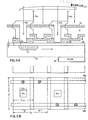
- the electrodes 53 together with the Si0 2 layer 54 and the substrate 55 constitute a MOS capacitor, under which, in response to the application of a negative bias to the electrodes 53, a potential well 57 is formed.
- the electrode structure schematically illustrated in Fig. 5A constitutes a so-called two-phase charge transfer circuit.
- Other prior art configurations of such charge transfer systems may also be used for the present invention. Details of these known circuits are contained, for example, in the following books:
- the charge that has accumulated in each detector after all detectors positioned underneath the 5 x 10 4 blind holes 58 have been simultaneously exposed by the electron beam is sequentially fed to the output circuits, amplified and converted into binary digits (0, 1) by suitable discriminator circuits (not shown).
- the output amplifiers are best integrated directly with the charge transfer system.
- the charge transfer device must be manufactured such that a high efficiency is obtained when the charge packages are transferred from one detector position to another (e.g., 99.9 %, as were previously achieved by prior art means); in addition, the dark current of the device, which occurs when electron hole pairs are generated by processes other than incident electrons, must be reduced to a minimum.-One way of reducing the dark current is to cool the silicon substrate 55, for example, by a Peltier element 59 connected thereto.
- the illumination time necessary for accumulating a sufficiently large charge in the potential wells is about 1 msec., even if electron beams with a low current strength are used for mask illumination to reduce the heating of the mask. For sequentially reading the stored charge image, a time of about 100 msec.
- the total time required for recording the mask image with a resolution of 0.5 ⁇ m is about 6 minutes.
- the thin metal layer at the base of the blind holes 58 is primarily used, as previously mentioned, to prevent electrostatic charges caused by the incident electron current; for tests carried out in practice, detector arrangements 40, whose blind holes were not provided with a metal layer, have already been used to good effect. At the small cross-section of these holes, the operation of the charge transfer circuit is not adversely affected if there is no metal layer (which also forms part of the electrode of the charge transfer device circuit).
- Blind holes with a metal layer may be readily produced, for instance, by the lift-off process.
- the wafer areas destined for the blind holes are covered with a photolithographically defined photoresist layer followed by an Si 3 N 4 layer.
- the photoresist is subsequently removed in a lift-off process, and a further thin metal (Al) film is deposited (by vapor deposition or cathode sputtering) covering the existing metal pattern and the bare portions of the wafer which form the base of the blind holes in later manufacturing steps.
- the thickness of the second metal layer is chosen suitably small.
Applications Claiming Priority (2)
| Application Number | Priority Date | Filing Date | Title |
|---|---|---|---|
| DE3410885 | 1984-03-24 | ||
| DE19843410885 DE3410885A1 (de) | 1984-03-24 | 1984-03-24 | Fehlerkorrigierte korpuskularstrahllithographie |
Publications (2)
| Publication Number | Publication Date |
|---|---|
| EP0158139A1 true EP0158139A1 (de) | 1985-10-16 |
| EP0158139B1 EP0158139B1 (de) | 1991-02-20 |
Family
ID=6231503
Family Applications (1)
| Application Number | Title | Priority Date | Filing Date |
|---|---|---|---|
| EP85102832A Expired - Lifetime EP0158139B1 (de) | 1984-03-24 | 1985-03-13 | Fehlerkorrigierte Korpuskularstrahl-Lithographie |
Country Status (4)
| Country | Link |
|---|---|
| US (1) | US4578587A (de) |
| EP (1) | EP0158139B1 (de) |
| JP (1) | JPS60201625A (de) |
| DE (2) | DE3410885A1 (de) |
Cited By (1)
| Publication number | Priority date | Publication date | Assignee | Title |
|---|---|---|---|---|
| EP0244816A2 (de) * | 1986-05-06 | 1987-11-11 | Hitachi, Ltd. | Gerät zum Nachweisen von Fehlern im Muster von Masken |
Families Citing this family (15)
| Publication number | Priority date | Publication date | Assignee | Title |
|---|---|---|---|---|
| JPS60201626A (ja) * | 1984-03-27 | 1985-10-12 | Canon Inc | 位置合わせ装置 |
| AT386297B (de) * | 1985-09-11 | 1988-07-25 | Ims Ionen Mikrofab Syst | Ionenstrahlgeraet und verfahren zur ausfuehrung von aenderungen, insbes. reparaturen an substraten unter verwendung eines ionenstrahlgeraetes |
| AT393925B (de) * | 1987-06-02 | 1992-01-10 | Ims Ionen Mikrofab Syst | Anordnung zur durchfuehrung eines verfahrens zum positionieren der abbildung der auf einer maske befindlichen struktur auf ein substrat, und verfahren zum ausrichten von auf einer maske angeordneten markierungen auf markierungen, die auf einem traeger angeordnet sind |
| AT392857B (de) * | 1987-07-13 | 1991-06-25 | Ims Ionen Mikrofab Syst | Vorrichtung und verfahren zur inspektion einer maske |
| US4885472A (en) * | 1988-03-14 | 1989-12-05 | The Perkin-Elmer Corporation | Silicon grid as a reference and calibration standard in a particle beam lithography system |
| US5180919A (en) * | 1990-09-18 | 1993-01-19 | Fujitsu Limited | Electron beam exposure system having the capability of checking the pattern of an electron mask used for shaping an electron beam |
| JP2725895B2 (ja) * | 1991-02-18 | 1998-03-11 | シャープ株式会社 | 露光機構 |
| JP3274212B2 (ja) * | 1993-03-18 | 2002-04-15 | 株式会社日立製作所 | 電子線検出器及びそれを用いた電子線描画装置 |
| JP2924635B2 (ja) * | 1994-03-16 | 1999-07-26 | 日本電気株式会社 | 半導体素子製造用レチクルおよび露光装置の製造誤差の補正方法 |
| JP2001519040A (ja) | 1995-08-30 | 2001-10-16 | ドイッチェ テレコム アーゲー | 三次元表面の構造化におけるコントラストを向上させる方法 |
| DE19630705A1 (de) | 1995-08-30 | 1997-03-20 | Deutsche Telekom Ag | Verfahren zur Herstellung von 3-dimensional strukturierten Polymerschichten für die integrierte Optik |
| US6144037A (en) * | 1998-06-18 | 2000-11-07 | International Business Machines Corporation | Capacitor charging sensor |
| US6353231B1 (en) | 1998-08-31 | 2002-03-05 | Nikon Corporation | Pinhole detector for electron intensity distribution |
| US7423269B1 (en) * | 2005-02-26 | 2008-09-09 | Kla-Tencor Technologies Corporation | Automated feature analysis with off-axis tilting |
| JPWO2016098174A1 (ja) * | 2014-12-15 | 2017-09-28 | ギガフォトン株式会社 | レーザ照射装置 |
Citations (7)
| Publication number | Priority date | Publication date | Assignee | Title |
|---|---|---|---|---|
| US3644700A (en) * | 1969-12-15 | 1972-02-22 | Ibm | Method and apparatus for controlling an electron beam |
| DE2702444A1 (de) * | 1977-01-20 | 1978-07-27 | Siemens Ag | Korpuskularstrahloptisches geraet zur abbildung einer maske auf ein praeparat |
| US4136285A (en) * | 1975-10-17 | 1979-01-23 | Siemens Aktiengesellschaft | Method for irradiating a specimen by corpuscular-beam radiation |
| US4140913A (en) * | 1977-01-20 | 1979-02-20 | Siemens Aktiengesellschaft | Charged-particle beam optical apparatus for the reduction imaging of a mask on a specimen |
| EP0063429A2 (de) * | 1981-04-16 | 1982-10-27 | Control Data Corporation | Elektronenstrahlmatrix-Lithographiegerät und Verwendungsverfahren desselben |
| DD201953A5 (de) * | 1980-10-15 | 1983-08-17 | Tokyo Shibaura Electric Co | Elektronenstrahlbelichtungssystem |
| US4438338A (en) * | 1981-11-05 | 1984-03-20 | Burr-Brown Research Corporation | Low profile optical coupling for an optoelectronic module |
Family Cites Families (4)
| Publication number | Priority date | Publication date | Assignee | Title |
|---|---|---|---|---|
| DE2739502C3 (de) * | 1977-09-02 | 1980-07-03 | Ibm Deutschland Gmbh, 7000 Stuttgart | Verfahren zur Belichtung durch Korpuskularstrahlen-Schattenwurf und Vorrichtung zur Durchführung des Verfahrens |
| DE2939044A1 (de) * | 1979-09-27 | 1981-04-09 | Ibm Deutschland Gmbh, 7000 Stuttgart | Einrichtung fuer elektronenstrahllithographie |
| US4443096A (en) * | 1981-05-18 | 1984-04-17 | Optimetrix Corporation | On machine reticle inspection device |
| US4438336A (en) * | 1982-03-26 | 1984-03-20 | Fraunhofer-Gesellschaft Zur Forderung Der Angewandten Forschung E.V. | Corpuscular radiation device for producing an irradiation pattern on a workpiece |
-
1984
- 1984-03-24 DE DE19843410885 patent/DE3410885A1/de not_active Withdrawn
- 1984-12-19 JP JP59266582A patent/JPS60201625A/ja active Granted
-
1985
- 1985-01-25 US US06/694,888 patent/US4578587A/en not_active Expired - Fee Related
- 1985-03-13 DE DE8585102832T patent/DE3581758D1/de not_active Expired - Fee Related
- 1985-03-13 EP EP85102832A patent/EP0158139B1/de not_active Expired - Lifetime
Patent Citations (7)
| Publication number | Priority date | Publication date | Assignee | Title |
|---|---|---|---|---|
| US3644700A (en) * | 1969-12-15 | 1972-02-22 | Ibm | Method and apparatus for controlling an electron beam |
| US4136285A (en) * | 1975-10-17 | 1979-01-23 | Siemens Aktiengesellschaft | Method for irradiating a specimen by corpuscular-beam radiation |
| DE2702444A1 (de) * | 1977-01-20 | 1978-07-27 | Siemens Ag | Korpuskularstrahloptisches geraet zur abbildung einer maske auf ein praeparat |
| US4140913A (en) * | 1977-01-20 | 1979-02-20 | Siemens Aktiengesellschaft | Charged-particle beam optical apparatus for the reduction imaging of a mask on a specimen |
| DD201953A5 (de) * | 1980-10-15 | 1983-08-17 | Tokyo Shibaura Electric Co | Elektronenstrahlbelichtungssystem |
| EP0063429A2 (de) * | 1981-04-16 | 1982-10-27 | Control Data Corporation | Elektronenstrahlmatrix-Lithographiegerät und Verwendungsverfahren desselben |
| US4438338A (en) * | 1981-11-05 | 1984-03-20 | Burr-Brown Research Corporation | Low profile optical coupling for an optoelectronic module |
Non-Patent Citations (1)
| Title |
|---|
| SOLID STATE TECHNOLOGY, September 1984 H. BOHLEN et al. "High Throughput Submicron Lithography with Electron Beam Proximity Printing" pages 210-217 * Fig. 2, 3, 11; page 214 * * |
Cited By (2)
| Publication number | Priority date | Publication date | Assignee | Title |
|---|---|---|---|---|
| EP0244816A2 (de) * | 1986-05-06 | 1987-11-11 | Hitachi, Ltd. | Gerät zum Nachweisen von Fehlern im Muster von Masken |
| EP0244816A3 (en) * | 1986-05-06 | 1989-11-23 | Hitachi, Ltd. | Pattern defect detection apparatus using scanning and transmission electron microscope |
Also Published As
| Publication number | Publication date |
|---|---|
| EP0158139B1 (de) | 1991-02-20 |
| DE3410885A1 (de) | 1985-10-03 |
| JPH0349421B2 (de) | 1991-07-29 |
| US4578587A (en) | 1986-03-25 |
| JPS60201625A (ja) | 1985-10-12 |
| DE3581758D1 (de) | 1991-03-28 |
Similar Documents
| Publication | Publication Date | Title |
|---|---|---|
| US4578587A (en) | Error-corrected corpuscular beam lithography | |
| US6465783B1 (en) | High-throughput specimen-inspection apparatus and methods utilizing multiple parallel charged particle beams and an array of multiple secondary-electron-detectors | |
| US5757409A (en) | Exposure method and pattern data preparation system therefor, pattern data preparation method and mask as well as exposure apparatus | |
| US6218671B1 (en) | On-line dynamic corrections adjustment method | |
| US20030215965A1 (en) | Method and apparatus for position measurement of a pattern formed by a lithographic exposure tool | |
| JP2005526269A (ja) | 空間画像を感知するシステム及び方法 | |
| EP0478215B1 (de) | Reflektionsmaske und eine solche Reflektionsmaske verwendendes geladenes Teilchenstrahl-Belichtungsgerät | |
| US6521900B1 (en) | Alignment marks for charged-particle-beam microlithography, and alignment methods using same | |
| US4385238A (en) | Reregistration system for a charged particle beam exposure system | |
| EP0033138B1 (de) | Verfahren zur Korrektur von Ablenkungsverzerrungen in einem Lithographiegerät mit geladenen Teilchen | |
| US4677296A (en) | Apparatus and method for measuring lengths in a scanning particle microscope | |
| US20080290288A1 (en) | Measurement System and a Method | |
| GB2109538A (en) | Electron beam alignment | |
| US3875414A (en) | Methods suitable for use in or in connection with the production of microelectronic devices | |
| US5712488A (en) | Electron beam performance measurement system and method thereof | |
| US5936252A (en) | Charged particle beam performance measurement system and method thereof | |
| JPH05190435A (ja) | 半導体装置の電子線描画方法 | |
| WO2000067291A2 (en) | Microfabricated template for multiple charged particle beam calibrations and shielded charged particle beam lithography | |
| TWI773329B (zh) | 圖案檢查裝置以及圖案檢查方法 | |
| US5160845A (en) | Alignment technique for masked ion beam lithography | |
| CN100442435C (zh) | 电子束描绘装置和电子束描绘方法 | |
| KR20210096226A (ko) | 스캐닝 하전 입자 현미경 교정 방법 | |
| JP2988884B2 (ja) | 荷電ビーム描画装置におけるビーム調整方法 | |
| US20150146179A1 (en) | Low energy electron beam lithography | |
| JP2001133234A (ja) | 欠陥検査方法、欠陥検査装置及びそれらを用いた半導体デバイスの製造方法 |
Legal Events
| Date | Code | Title | Description |
|---|---|---|---|
| PUAI | Public reference made under article 153(3) epc to a published international application that has entered the european phase |
Free format text: ORIGINAL CODE: 0009012 |
|
| AK | Designated contracting states |
Designated state(s): DE FR GB |
|
| 17P | Request for examination filed |
Effective date: 19850813 |
|
| 17Q | First examination report despatched |
Effective date: 19880719 |
|
| GRAA | (expected) grant |
Free format text: ORIGINAL CODE: 0009210 |
|
| AK | Designated contracting states |
Kind code of ref document: B1 Designated state(s): DE FR GB |
|
| REF | Corresponds to: |
Ref document number: 3581758 Country of ref document: DE Date of ref document: 19910328 |
|
| ET | Fr: translation filed | ||
| PLBE | No opposition filed within time limit |
Free format text: ORIGINAL CODE: 0009261 |
|
| STAA | Information on the status of an ep patent application or granted ep patent |
Free format text: STATUS: NO OPPOSITION FILED WITHIN TIME LIMIT |
|
| 26N | No opposition filed | ||
| PGFP | Annual fee paid to national office [announced via postgrant information from national office to epo] |
Ref country code: FR Payment date: 19950228 Year of fee payment: 11 |
|
| PGFP | Annual fee paid to national office [announced via postgrant information from national office to epo] |
Ref country code: DE Payment date: 19950330 Year of fee payment: 11 |
|
| PG25 | Lapsed in a contracting state [announced via postgrant information from national office to epo] |
Ref country code: FR Effective date: 19961129 |
|
| PG25 | Lapsed in a contracting state [announced via postgrant information from national office to epo] |
Ref country code: DE Effective date: 19961203 |
|
| REG | Reference to a national code |
Ref country code: FR Ref legal event code: ST |
|
| PGFP | Annual fee paid to national office [announced via postgrant information from national office to epo] |
Ref country code: GB Payment date: 19970224 Year of fee payment: 13 |
|
| PG25 | Lapsed in a contracting state [announced via postgrant information from national office to epo] |
Ref country code: GB Free format text: LAPSE BECAUSE OF NON-PAYMENT OF DUE FEES Effective date: 19980313 |
|
| GBPC | Gb: european patent ceased through non-payment of renewal fee |
Effective date: 19980313 |