EP0418496B1 - Elektrisches Installationsgerät, insbesondere Schutzkontaktsteckdose - Google Patents
Elektrisches Installationsgerät, insbesondere Schutzkontaktsteckdose Download PDFInfo
- Publication number
- EP0418496B1 EP0418496B1 EP90113924A EP90113924A EP0418496B1 EP 0418496 B1 EP0418496 B1 EP 0418496B1 EP 90113924 A EP90113924 A EP 90113924A EP 90113924 A EP90113924 A EP 90113924A EP 0418496 B1 EP0418496 B1 EP 0418496B1
- Authority
- EP
- European Patent Office
- Prior art keywords
- installation apparatus
- support ring
- insulating material
- base
- housing
- Prior art date
- Legal status (The legal status is an assumption and is not a legal conclusion. Google has not performed a legal analysis and makes no representation as to the accuracy of the status listed.)
- Expired - Lifetime
Links
Images

Classifications
-
- H—ELECTRICITY
- H01—ELECTRIC ELEMENTS
- H01R—ELECTRICALLY-CONDUCTIVE CONNECTIONS; STRUCTURAL ASSOCIATIONS OF A PLURALITY OF MUTUALLY-INSULATED ELECTRICAL CONNECTING ELEMENTS; COUPLING DEVICES; CURRENT COLLECTORS
- H01R13/00—Details of coupling devices of the kinds covered by groups H01R12/70 or H01R24/00 - H01R33/00
- H01R13/66—Structural association with built-in electrical component
- H01R13/665—Structural association with built-in electrical component with built-in electronic circuit
- H01R13/6691—Structural association with built-in electrical component with built-in electronic circuit with built-in signalling means
Definitions
- the invention relates to an electrical installation device, in particular a protective contact socket, with an insulating base held by a supporting ring having supporting webs, which in addition to the electrical contacts, the earthing clip and mechanical holding elements additionally has a circuit board with surge protection elements, the effectiveness of which can be indicated by a signaling device assigned to the circuit board , wherein the support ring can be connected to a receptacle comprising these components, such as a flush-mounted box.
- Electrical installation devices of this type are known in numerous embodiments. They have the advantage in themselves that they protect the devices connected to the socket from overvoltage. This is because they have a circuit board with overvoltage protection elements in the area of their insulating base. These can be destroyed in the event of very high-energy overvoltages, so that the protective circuit becomes inoperative.
- the optical signaling devices are difficult for the user to recognize, in the other case, when there are many indicator lamps in the same room, it can easily be overlooked that the red lamp of the installation device lights up and indicates that the overvoltage protection element is defective.
- an acoustic signaling device is used as the signaling device.
- a socket with surge protection with an acoustic display of a defect in the surge protection is known.
- This document relates to a socket with overvoltage protection, which is installed on or in the socket base, for example in the form of an additional module attached to the socket base, whereby a defect in the overvoltage protection is indicated.
- an acoustic display is provided as the display and that the means of this acoustic display are in the socket or on or in the socket base.
- an acoustic signal device has considerable advantages over the known optical signal devices. Since an acoustic signaling device e.g. emits a continuous tone, it is practically impossible for the user of such an electrical socket that he is not made aware that the overvoltage protection device of the installation device has failed and that remedial action must therefore be taken. Such an acoustic signal device is unmistakable not only in very bright rooms, but also in rooms with many display devices.
- an electronic, acoustic signal transmitter of known design is proposed, but it is also provided that signal transmitters are known as so-called buzzers.
- the invention now seeks to remedy this. It is based on the object of providing an encapsulated structural unit in the case of an installation device with an overvoltage protection device and a signal device of the type specified, which can be attached to existing components of the installation device without separate connecting means.
- the insulating base and the circuit board with the components assigned to it are surrounded by an insulating housing which can be fixed on existing receptacles of the supporting ring of the socket.
- the electrical installation device designed according to the invention has considerable advantages over the known embodiments since, on the one hand, suitable protection of the insulating base of the circuit board with the overvoltage protection elements and the signaling device is guaranteed against damage during storage and transport. Furthermore, the already existing receptacles or openings on the support ring, for example the socket, serve to fix them on the installation device. As a result, neither a change in the insulating material base nor in the support ring of the electrical installation device is necessary, so that the existing production tools can continue to be used for such an installation device.
- the insulating material housing is fastened to the retaining webs of the support ring of the installation device.
- Such a fastening is preferred in which the usual expanding claws of the retaining webs of the support ring are removed.
- the boundary walls of the openings provided for the expanding claws now serve as counter-latching for latching the insulating material housing.
- the expansion claws can be removed without any problems because they are usually detachably attached to the base by means of a screw. By removing this fastening screw, you can remove the expansion claw without having to change the insulating base.
- the breakthrough in the retaining web is free and can be used as a counter-catch according to the invention.
- Such a counter-latching means that there is no change compared to the previous design of the retaining web. With this counter detent, a detent of the insulating material housing interacts.
- the side walls of the insulating material housing weighed arms on diametrically opposite areas, each of which has a molded catch at its free ends.
- the bent arms of the insulating material housing can also be produced during its manufacture. The strength of the bend is chosen so that the hooks on the front free end of the arms come into good operative contact with the counter-catches in the area of the openings of the holding webs. In this way, a snap connection is created with simple means, which also has the advantage that it can be released again if necessary.
- the insulating material housing is fixed on the insulating base by means of fastening pins.
- the one ends of such fastening pins are equipped with retaining projections; these each penetrate an opening in the angled end of the retaining web after they have previously been inserted through an already existing opening in the base.
- the holding projections then interact with the boundary walls of the opening of the angled end of the holding web in the sense of a retention.
- the opposite other end of each fastening pin passes through the bottom of the insulating material housing and is fixed on the outside of the bottom. This can be done, for example, by a locking element, such as a locking washer.
- each fastening pin at its end facing the insulating material base, one behind the other on its circumferential surface in the axial direction, several, preferably regularly arranged and mutually identical retaining projections. Of each of these retaining projections then comes into operative connection with the boundary walls of the opening of the angled end of the retaining web mentioned. In this way, for example, an adaptation to the insulating base with different heights can be achieved.
- each fastening pin passes through an elongated hole in the bottom of the insulating material housing in order to enable a change in their mutual distance.
- These elongated holes thus make it possible to increase or decrease the mutual distance between the two existing fastening pins, of course only to the extent that the length of the elongated holes permits.
- each fastening pin free of the holding projections, is surrounded by a spring.
- This is supported at one end on the inner surface of the bottom of the insulating material housing, while its other end presses against the circuit board, optionally with the interposition of a washer, which carries the overvoltage protection elements and the acoustically acting signaling device.
- a washer which carries the overvoltage protection elements and the acoustically acting signaling device.
- the insulating material housing has at least on two diametrically opposite sides of its circumferential surface a fastening arm, each of which is present in the support ring Reaches through holes.
- the area of the fastening arm which projects out of the supporting ring plane after reaching through has a holding element which is supported on the outside of the supporting ring.
- This holding element can be designed and designed differently. It can be a separate holding element which, for example, penetrates an opening in the part of the fastening arm projecting from the support ring plane and lies transversely over the boundary edges of the respective hole in the support ring. In this way, a return movement of the mounting arm is avoided.
- the end of the fastening arm projecting beyond the support ring plane is at the same time designed as a fastening element which interacts with the support ring.
- the fastening end of each fastening arm of the insulating material housing is expediently widened by forming a head in such a way that the width of this head projects beyond both the hole in the supporting ring and the widening thereof that follows.
- the insulating material housing has holding strips for the circuit board of the overvoltage protection elements or the acoustic signal device lying on its inner wall below the bottom of the insulating material base. There can be holding strips arranged in pairs, which have a mutual spacing corresponding to the thickness of the board. In this way, the end of the circuit board can be inserted into the gap between the retaining strips arranged in pairs and secured in position.
- FIG. 1 of the drawing shows a first embodiment of the electrical installation device according to the invention, namely in the form of a protective contact socket generally designated 10.
- This protective contact socket 10 includes a one-piece support ring 11 made of a metallic material, which has retaining webs 12 bent approximately at right angles on two diametrically opposite sides; these pass into an angled end denoted by 14. with its outside, the angled end 14 lies on the facing surface of a basically known insulating base 16.
- fastening screws 15 are used which pass through an opening 35 in the angled end 14 of the retaining web 12 and with its shaft end in a blind hole in the insulating base 16.
- the support ring 11 is a commercially available embodiment, but differs from it in that it differs in that it exists Spreading claws have been removed. These expanding claws normally pass through an opening 13 in the retaining web 12 with their rear end, the rear end being able to cooperate with a screw, such that when the screw is actuated the expanding claw is moved outwards with its pointed claw to the outer surface of a can , for example a flush-mounted box, to be able to interact.
- This expanding claw and the fastening screw assigned to it are omitted in the embodiment of the support ring according to FIG. 1. As far as the hole for the screw of the expanding claw is concerned, this is now used to accommodate the fastening screw 15.
- the opening 13 of the holding web is also used in a conventional design. However, it now has a different function. It serves namely with its boundary walls as a counter-catch for receiving a catch 27, which is part of an insulating material housing generally designated 25.
- This latch 27 sits at the end of a bent arm 26 of the insulating housing 25.
- the arms 26 are provided on the side walls of the insulating housing 25 on two diametrically opposite sides, which are bent by approximately 45 ° from the plane of the side wall, and which their front free end each carry a catch 27 which engages through the opening 13 of the holding web 12 in the manner shown in Fig. 1 and thereby cooperates with the counter-catches of the holding web 12, which, as said, are formed by the boundary walls of this opening 13.
- the insulating base 16 also has a commercially available Education. It is made in one piece from one of the insulating materials commonly used in the electrical industry; it is used, among other things, to accommodate the contacts and the earthing bracket. Only a few of the electrical devices carried by the insulating base 16 are shown. So raised walls 17 are provided from the level of the insulating material base in the direction of the support ring 11, which limit recordings. First there is the receptacle 18, which is used to accommodate the connection contacts, not shown. These contacts also include the resilient parts that are used to engage the plug, not shown.
- the receptacle lying in the middle of the insulating base 16 is designated 19; this serves to accommodate a grounding bracket 20, which is generally firmly connected to the insulating base 16 with a rivet, not shown, in the middle thereof. To the right and left of the web of the earthing bracket 20, the earthing screws 21 are attached, of which only one is shown in FIG. 1. The connecting cables on the base are missing.
- a board 23 is arranged beneath the base 16, the length of which corresponds approximately to that of the insulating base 16, this serves for the storage of overvoltage protection elements.
- These surge protection elements, which are attached to the circuit board 23, have a basically known design. Their intended use is also known, so that their graphic representation is largely dispensed with.
- this board 23 is now assigned an acoustic signaling device designated by 24 which is shown schematically, since its structure is also known in principle.
- it can be electronic, acoustic signal transmitter, which are known under the name buzzer.
- the circuit board 23 can be connected to the inner walls of the insulating material housing 25 at a distance from the insulating material base 16 using basically known fastening means; Clamp connections, adhesive connections, snap connections or the like may be mentioned, for example.
- Clamp connections, adhesive connections, snap connections or the like may be mentioned, for example.
- the insulating material housing designated by 25 is an approximately U-shaped body when viewed in cross section, the bottom 36 of which forms the web of this U.
- the side walls, which correspond to the leg of the U's, are raised in the exemplary embodiment according to FIG. 1 approximately to the level of the underside of the support ring 11.
- all parts located on the insulating base 16 are thus surrounded by the insulating housing 25. Only areas in which the bent arms 26 lie are left free.
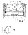
- the horizontally lying area of the support ring 11 is provided in a generally known manner with a total of four holes 44; one of these is shown in FIG. 5 of the drawing. It follows that each hole 44 has curved boundary walls, and that the hole 44 merges at one end into a circular extension 45 when viewed in plan view.
- a hole 44 of the support ring 11 can now be used to connect this support ring to a box 28, which in the exemplary embodiment according to FIG. 1 of the drawing is designed as a flush-mounted box.
- the connection between the support ring 11 and the flush-mounted box 28 takes place by means of retaining screws 30 which pass through two diametrically opposite holes 44 of the support ring and each engage with its shaft in a blind hole 29 of the flush-mounted box 46.
- the flush-mounted box 28 has such a large wall thickness that the blind holes 29 can easily be accommodated in them, as the drawing shows. If necessary, however, it is also possible to use thin-walled ones instead of such flush-mounting boxes. In this case, in order to create accommodation spaces for the shafts of the holding screws 30, domes are used which in turn receive the blind holes 29. It is possible to form these domes on both the outside and the inside of the side wall of the flush-mounted box.
- FIG. 1 It is not shown in FIG. 1 to draw in the wall which has an opening in which the flush-mounted box 28 is accommodated. This can be done in a known manner.
- the box 28 does not always have to be a flush-mounted box, rather it is also possible to use a surface-mounted box for this.
- such cans can be used, or the like in connection with cable ducts. are used.
- the box-like design of the receiving space for the insulating material housing 25 and the parts lying inside it is also conceivable.
- Electrical installation device is assigned an acoustic signal device 24 which emits an acoustic signal in the event of overvoltages and the resulting destruction of overvoltage protection elements, which cannot be missed by the user, and which indicates that the protective elements of the circuit board are ineffective. The user can then react accordingly and, for example, replace the circuit board or the entire base.
- a second embodiment of the electrical installation device according to the invention is shown; this in turn is designed as a protective contact socket 10.
- No changes have been made to the design of the insulating base and that of the socket 28.
- the attachment of the insulating material housing 25 to the insulating material base 16 has changed.
- the insulating material base 16 is again held by the supporting ring 11, using the holding webs 12.
- the openings 13 in the holding webs 12 are at this embodiment is of no importance.
- the expanding claws are also removed in this exemplary embodiment because they are not used to establish a connection between the support ring and the inner wall of the box 28. Instead, the support ring 11 is in turn connected to the socket 28 via the retaining screws 30.
- each retaining web is provided with an opening 33 which, however, no longer interacts with a fastening screw 15, as in the first exemplary embodiment, but now with the upper part of a fastening pin, generally designated 31.
- This mounting pin 31 has on the peripheral surface lying in its upper part, a plurality of holding projections 32 which are arranged all around and are arranged one behind the other in a regular arrangement in the longitudinal direction of the fastening pin 31.
- the holding projections 32 have the same configuration with one another, which facilitates production.
- One of these retaining projections 32 interacts with the boundary walls of the opening 33 of the angled end 14 of the retaining web 12 of the support ring 11. In this way, a connection between the fastening pin 31 and the insulating base 16 is established.
- the fastening pin 31 also passes through a bore in the insulating base 16, which is not described in any more detail, and, on the other hand, also a bore of the circuit board 23, which is also not shown.
- the lower end of the fastening pin 31 is free of retaining projections 32, and it is thus kept smooth-walled.
- the fastening pin engages with its lower end 35 elongated holes 37, which are provided in the bottom 36 of the insulating material housing 35.
- a locking washer 38 is placed which exceeds the dimensions of the elongated hole 37 and can therefore lay against the outside of the bottom 36 of the insulating material housing.
- the lower end 35 of the fastening pin 31 is also surrounded by a spring, generally designated 39, which is designed as a compression spring, that is to say the lower end 35 of the fastening pin 31 lies in the interior of this spring 39.
- a spring 39 which is designed as a compression spring, that is to say the lower end 35 of the fastening pin 31 lies in the interior of this spring 39.
- One end of the spring 39 is supported thereby on the inside of the bottom 36 of the insulating material housing, the other end against a washer 34, which in turn rests on the underside of the board 23.
- the springs 39 which find an abutment on the base 36, is carried out via the washer 34 pressing the circuit board 23 and thus the acoustic signal device 24 onto the outside of the insulating base 16.
- Fig. 3 of the drawing the formation of one of the elongated holes 37 can be seen, which are penetrated by the fastening pin 31.
- the mutual distance between the two existing fastening pins 31 can be varied.
- the two fastening pins have approximately their smallest mutual distance. This can be increased by moving the fastening pins 31 in the elongated hole 37 apart on different sides until the peripheral surface of the fastening pin strikes the boundary edge of the elongated holes 37.
- the insulating housing 25 is kept much smaller in length.
- the side walls of the insulating material housing only protrude approximately to the height of the lower angled end 14 of the holding web 12.
- the peripheral surface of the insulating material housing can be held continuously; In this case, only the bottom 36 is broken, namely by the two elongated holes 37 spaced apart from one another.
- FIG. 4 a third embodiment of the electrical installation device according to the invention is shown.
- this electrical installation device is again a safety socket. 4 differs from FIGS. 1 and 2 in that the section through the parts of the protective contact socket is offset by 90 °. As a result, the earthing bracket 20 has now become visible in FIG. 4.
- the insulating base 16 has maintained its training.
- the circuit board 23 with the acoustic signal device 24 is also not directly connected to the bottom of the insulating base 16 here, but is at a distance below it.
- 25 retaining strips 41 are attached to the inner walls of the insulating material housing. In the selected embodiment, these are present in pairs, such that they enclose a gap between them, the dimensions of which are adapted to the thickness of the board 23.
- the insulating material housing 25 has at least two fastening arms 42 on at least two diametrically opposite sides of its peripheral surface. In the exemplary embodiment, this is bent outwards from the basic plane of the peripheral surface of the insulating material housing 25, to the extent that that the mounting arm 42 comes to rest in the area of a hole 44 of the support ring 11.
- the mounting arm 42 is dimensioned so long that it can pass through a hole 44 of this support ring 11.
- the area of the fastening arm 42 protruding from the support ring plane has a holding element which is supported on the outside of the support ring.
- each fastening arm 42 projecting beyond the support ring plane is at the same time designed as a fastening end 43 which interacts with the support ring 11.
- the fastening end 43 of each fastening arm 42 of the insulating housing 45 is widened by forming a head in such a way that the width of this head projects beyond both the hole 44 and the widening 45 adjoining it.
- This training can best be seen from FIG. 5 of the drawing.
- any known acoustically operating signaling device can be used as a signaling device, insofar as its external one Dimensions are such that they can be accommodated in the gap between the board 23 and the bottom of the insulating housing 25.
- the size of this gap can still be varied by, for example, placing the bottom 36 of the insulating material housing higher than shown. In this way, the prescribed distance between the underside of the bottom 36 of the insulating material housing and the bottom of the flush-mounted box 28, not shown.
- the box - as in the exemplary embodiments - is designed as a flush-mounted box 28. Rather, it can also be a surface-mounted box or a cable box, ie one that is used in connection with cable ducts.
- the term “can” should also include box-shaped embodiments. A circular design of the can in cross section is therefore not necessary. However, this is preferred because in practice, circular designs of the flush-mounted box are generally used in cross-section. It is also advantageous that the manufacturing tools previously used for the parts of the safety socket can continue to be used. For example, this applies to the support ring.
- the removal of the expanding claws does not change anything because these expanding claws are not an integral part of the support ring but instead only grip through the opening of the retaining web with one leg, in order then to be fastened to the insulating base 16 using one screw each.
- the insulating base 16 can also have a known design. If necessary, it must still be on its underside be equipped with fasteners to hold the board in place. However, this only applies to some of the versions shown. Not, for example, for the one according to FIGS. 2 and 4 of the drawing. In the former case, the cohesion between the circuit board 23 and the insulating base 16 takes place by the force of the springs 39. In the case of the embodiment according to FIG. 4 of the drawing, the circuit board 23 is not connected directly to the insulating base at all, but to the inner wall of the insulating material housing using it of holding bars.
- the flush-mounted box 28 can also be configured differently from the one shown. In particular, it can be kept much thinner. In this case, fastening domes are to be molded onto the inner walls in order to make room for the accommodation of the blind holes 29 for receiving the retaining screws 3o.
Applications Claiming Priority (2)
| Application Number | Priority Date | Filing Date | Title |
|---|---|---|---|
| DE3929229A DE3929229C2 (de) | 1989-09-02 | 1989-09-02 | Steckdose, insbesondere Schutzkontaktsteckdose |
| DE3929229 | 1989-09-02 |
Publications (2)
| Publication Number | Publication Date |
|---|---|
| EP0418496A1 EP0418496A1 (de) | 1991-03-27 |
| EP0418496B1 true EP0418496B1 (de) | 1995-01-25 |
Family
ID=6388532
Family Applications (1)
| Application Number | Title | Priority Date | Filing Date |
|---|---|---|---|
| EP90113924A Expired - Lifetime EP0418496B1 (de) | 1989-09-02 | 1990-07-20 | Elektrisches Installationsgerät, insbesondere Schutzkontaktsteckdose |
Country Status (3)
| Country | Link |
|---|---|
| EP (1) | EP0418496B1 (un) |
| AT (1) | ATE117844T1 (un) |
| DE (1) | DE3929229C2 (un) |
Families Citing this family (4)
| Publication number | Priority date | Publication date | Assignee | Title |
|---|---|---|---|---|
| DE29507448U1 (de) * | 1995-05-04 | 1995-06-29 | Kleinhuis Hermann Gmbh | Steckdose, insbesondere Schutzkontaktsteckdose |
| DE29601440U1 (de) * | 1996-01-29 | 1997-05-28 | Dehn & Soehne | Steckdose mit einem Modul für Zusatzfunktionen |
| DE19728537A1 (de) * | 1997-07-04 | 1999-01-07 | Abb Patent Gmbh | Elektrische Steckdose |
| DE102007042380A1 (de) | 2007-09-06 | 2009-03-12 | Pero Nilovic | Elektrische Überspannungsschutz-Baueinheit |
Family Cites Families (8)
| Publication number | Priority date | Publication date | Assignee | Title |
|---|---|---|---|---|
| DE3145308A1 (de) * | 1981-11-14 | 1983-05-26 | Gebrüder Merten GmbH & Co KG, 5270 Gummersbach | Elektrische steckdose |
| DE3212095C2 (de) * | 1982-04-01 | 1984-09-27 | Brunnquell GmbH Fabrik elektrotechnischer Apparate, 8070 Ingolstadt | Elektromechanischer Überlastanzeiger |
| NL8502493A (nl) * | 1985-09-11 | 1987-04-01 | Elektrotechnisch Installatiebu | Stelsel voor het tegen diefstal beveiligen van elektrische toestellen, en voor dit stelsel bestemde wandcontactdoos. |
| DE8703060U1 (un) * | 1987-02-27 | 1987-04-23 | Obo Bettermann Ohg, 5750 Menden, De | |
| DE3706419A1 (de) * | 1987-02-27 | 1988-09-08 | Bettermann Obo Ohg | Ueberspannungsschutzgeraet |
| DE3736945A1 (de) * | 1987-03-10 | 1988-09-22 | Dehn & Soehne | Steckdose mit zusatzmodul |
| DE8805235U1 (un) * | 1988-04-20 | 1988-06-16 | Gebr. Vedder Gmbh, 5885 Schalksmuehle, De | |
| DE3840198A1 (de) * | 1988-11-29 | 1990-05-31 | Dehn & Soehne | Steckdose mit ueberspannungsschutz |
-
1989
- 1989-09-02 DE DE3929229A patent/DE3929229C2/de not_active Expired - Fee Related
-
1990
- 1990-07-20 EP EP90113924A patent/EP0418496B1/de not_active Expired - Lifetime
- 1990-07-20 AT AT90113924T patent/ATE117844T1/de not_active IP Right Cessation
Also Published As
| Publication number | Publication date |
|---|---|
| DE3929229A1 (de) | 1991-03-14 |
| ATE117844T1 (de) | 1995-02-15 |
| EP0418496A1 (de) | 1991-03-27 |
| DE3929229C2 (de) | 1994-11-17 |
Similar Documents
| Publication | Publication Date | Title |
|---|---|---|
| EP3117112B1 (de) | Befestigungssystem zum montieren von geräten, insbesondere elektrogeräten | |
| DE19854666A1 (de) | Signaleinrichtung | |
| DE69822086T2 (de) | Elektrische Anschlusseinheit mit einem eine verlängerte Seitenwand aufweisenden Verbindungsblock | |
| EP0600109A1 (de) | Kabelkanal, wie Installationskanal | |
| EP0418496B1 (de) | Elektrisches Installationsgerät, insbesondere Schutzkontaktsteckdose | |
| EP2994927A1 (de) | Kippschalter für mehrere schaltstellungen | |
| DE2912208A1 (de) | Elektrisches geraet, insbesondere installationsgeraet | |
| EP0649192B1 (de) | Elektrisches Installationsgerät mit Zusatzmodul | |
| EP0148334A2 (de) | Anordnung zur Halterung von Zubehör an einer Leuchtenwand | |
| DE102006060231B4 (de) | Elektrisches/elektronisches Installationsgerät | |
| DE102009049407A1 (de) | Elektroinstallationsgerät mit einstellbarem Schaltelement | |
| DE3241407C1 (de) | Anzeige- und Bedientableau fuer Aufzugkabinen | |
| DE3728749A1 (de) | Elektrisches installationsgeraet, wie steckdose, insbesondere schutzkontaktsteckdose | |
| DE19527013C2 (de) | Unterputzgeräte-Mehrfachkombination | |
| DE3802971C2 (de) | Elektrisches Installationsgerät, wie Schalter, Taster, Tastschalter od. dgl. | |
| DE7707498U1 (de) | Tragorgan für elektrische Installationsgeräte, wie Schalter oder Steckdose | |
| EP0149809A1 (de) | Anordnung zum Sichern einer Verbindung | |
| DE19653319C2 (de) | Elektrische Verbindungsdose, wie Schalterdose, Abzweigdose od.dgl. | |
| WO2008061596A1 (de) | Staubschutzeinrichtung für ein melde- und/oder befehlsgerät | |
| DE2500295A1 (de) | Vorrichtung an einer elektrischen apparatedose | |
| AT401698B (de) | Einbaudose, insbesondere unterputzdose | |
| DE3401172C2 (un) | ||
| EP0111156A1 (de) | Adapter für automatische Brandmelder und Adapter mit Melderfassung zur Montage auf bereits installierte Meldersockel | |
| DE2459780A1 (de) | Elektrisches installationsgeraet | |
| DE3145103A1 (de) | Elektrisches installations-schaltgeraet mit aufsteckbarer sockelverkleidung |
Legal Events
| Date | Code | Title | Description |
|---|---|---|---|
| PUAI | Public reference made under article 153(3) epc to a published international application that has entered the european phase |
Free format text: ORIGINAL CODE: 0009012 |
|
| AK | Designated contracting states |
Kind code of ref document: A1 Designated state(s): AT BE CH ES FR GB IT LI NL SE |
|
| 17P | Request for examination filed |
Effective date: 19910507 |
|
| 17Q | First examination report despatched |
Effective date: 19931201 |
|
| GRAA | (expected) grant |
Free format text: ORIGINAL CODE: 0009210 |
|
| AK | Designated contracting states |
Kind code of ref document: B1 Designated state(s): AT BE CH ES FR GB IT LI NL SE |
|
| PG25 | Lapsed in a contracting state [announced via postgrant information from national office to epo] |
Ref country code: IT Free format text: LAPSE BECAUSE OF FAILURE TO SUBMIT A TRANSLATION OF THE DESCRIPTION OR TO PAY THE FEE WITHIN THE PRESCRIBED TIME-LIMIT;WARNING: LAPSES OF ITALIAN PATENTS WITH EFFECTIVE DATE BEFORE 2007 MAY HAVE OCCURRED AT ANY TIME BEFORE 2007. THE CORRECT EFFECTIVE DATE MAY BE DIFFERENT FROM THE ONE RECORDED. Effective date: 19950125 Ref country code: GB Effective date: 19950125 Ref country code: FR Effective date: 19950125 Ref country code: ES Free format text: THE PATENT HAS BEEN ANNULLED BY A DECISION OF A NATIONAL AUTHORITY Effective date: 19950125 Ref country code: BE Effective date: 19950125 |
|
| REF | Corresponds to: |
Ref document number: 117844 Country of ref document: AT Date of ref document: 19950215 Kind code of ref document: T |
|
| PG25 | Lapsed in a contracting state [announced via postgrant information from national office to epo] |
Ref country code: SE Effective date: 19950425 |
|
| EN | Fr: translation not filed | ||
| GBV | Gb: ep patent (uk) treated as always having been void in accordance with gb section 77(7)/1977 [no translation filed] |
Effective date: 19950125 |
|
| PLBE | No opposition filed within time limit |
Free format text: ORIGINAL CODE: 0009261 |
|
| STAA | Information on the status of an ep patent application or granted ep patent |
Free format text: STATUS: NO OPPOSITION FILED WITHIN TIME LIMIT |
|
| 26N | No opposition filed | ||
| PGFP | Annual fee paid to national office [announced via postgrant information from national office to epo] |
Ref country code: CH Payment date: 19990616 Year of fee payment: 10 |
|
| PGFP | Annual fee paid to national office [announced via postgrant information from national office to epo] |
Ref country code: NL Payment date: 19990730 Year of fee payment: 10 |
|
| PG25 | Lapsed in a contracting state [announced via postgrant information from national office to epo] |
Ref country code: LI Free format text: LAPSE BECAUSE OF NON-PAYMENT OF DUE FEES Effective date: 20000731 Ref country code: CH Free format text: LAPSE BECAUSE OF NON-PAYMENT OF DUE FEES Effective date: 20000731 |
|
| PG25 | Lapsed in a contracting state [announced via postgrant information from national office to epo] |
Ref country code: NL Free format text: LAPSE BECAUSE OF NON-PAYMENT OF DUE FEES Effective date: 20010201 |
|
| REG | Reference to a national code |
Ref country code: CH Ref legal event code: PL |
|
| NLV4 | Nl: lapsed or anulled due to non-payment of the annual fee |
Effective date: 20010201 |
|
| PGFP | Annual fee paid to national office [announced via postgrant information from national office to epo] |
Ref country code: AT Payment date: 20030725 Year of fee payment: 14 |
|
| PG25 | Lapsed in a contracting state [announced via postgrant information from national office to epo] |
Ref country code: AT Free format text: LAPSE BECAUSE OF NON-PAYMENT OF DUE FEES Effective date: 20040720 |