EP0981019A1 - Method and burner for combustion of liquid fuels - Google Patents
Method and burner for combustion of liquid fuels Download PDFInfo
- Publication number
- EP0981019A1 EP0981019A1 EP98810815A EP98810815A EP0981019A1 EP 0981019 A1 EP0981019 A1 EP 0981019A1 EP 98810815 A EP98810815 A EP 98810815A EP 98810815 A EP98810815 A EP 98810815A EP 0981019 A1 EP0981019 A1 EP 0981019A1
- Authority
- EP
- European Patent Office
- Prior art keywords
- fuel
- air inlet
- burner
- combustion
- air
- Prior art date
- Legal status (The legal status is an assumption and is not a legal conclusion. Google has not performed a legal analysis and makes no representation as to the accuracy of the status listed.)
- Withdrawn
Links
Images

Classifications
-
- F—MECHANICAL ENGINEERING; LIGHTING; HEATING; WEAPONS; BLASTING
- F23—COMBUSTION APPARATUS; COMBUSTION PROCESSES
- F23D—BURNERS
- F23D11/00—Burners using a direct spraying action of liquid droplets or vaporised liquid into the combustion space
- F23D11/36—Details, e.g. burner cooling means, noise reduction means
- F23D11/40—Mixing tubes or chambers; Burner heads
- F23D11/402—Mixing chambers downstream of the nozzle
-
- F—MECHANICAL ENGINEERING; LIGHTING; HEATING; WEAPONS; BLASTING
- F23—COMBUSTION APPARATUS; COMBUSTION PROCESSES
- F23C—METHODS OR APPARATUS FOR COMBUSTION USING FLUID FUEL OR SOLID FUEL SUSPENDED IN A CARRIER GAS OR AIR
- F23C7/00—Combustion apparatus characterised by arrangements for air supply
- F23C7/002—Combustion apparatus characterised by arrangements for air supply the air being submitted to a rotary or spinning motion
-
- F—MECHANICAL ENGINEERING; LIGHTING; HEATING; WEAPONS; BLASTING
- F23—COMBUSTION APPARATUS; COMBUSTION PROCESSES
- F23D—BURNERS
- F23D11/00—Burners using a direct spraying action of liquid droplets or vaporised liquid into the combustion space
- F23D11/36—Details, e.g. burner cooling means, noise reduction means
- F23D11/38—Nozzles; Cleaning devices therefor
-
- B—PERFORMING OPERATIONS; TRANSPORTING
- B05—SPRAYING OR ATOMISING IN GENERAL; APPLYING FLUENT MATERIALS TO SURFACES, IN GENERAL
- B05B—SPRAYING APPARATUS; ATOMISING APPARATUS; NOZZLES
- B05B1/00—Nozzles, spray heads or other outlets, with or without auxiliary devices such as valves, heating means
- B05B1/02—Nozzles, spray heads or other outlets, with or without auxiliary devices such as valves, heating means designed to produce a jet, spray, or other discharge of particular shape or nature, e.g. in single drops, or having an outlet of particular shape
- B05B1/04—Nozzles, spray heads or other outlets, with or without auxiliary devices such as valves, heating means designed to produce a jet, spray, or other discharge of particular shape or nature, e.g. in single drops, or having an outlet of particular shape in flat form, e.g. fan-like, sheet-like
-
- F—MECHANICAL ENGINEERING; LIGHTING; HEATING; WEAPONS; BLASTING
- F23—COMBUSTION APPARATUS; COMBUSTION PROCESSES
- F23C—METHODS OR APPARATUS FOR COMBUSTION USING FLUID FUEL OR SOLID FUEL SUSPENDED IN A CARRIER GAS OR AIR
- F23C2900/00—Special features of, or arrangements for combustion apparatus using fluid fuels or solid fuels suspended in air; Combustion processes therefor
- F23C2900/07002—Premix burners with air inlet slots obtained between offset curved wall surfaces, e.g. double cone burners
Definitions
- the present invention relates to a method for the combustion of liquid Fuels in a burner according to the preamble of claim 1. It concerns also a burner for applying the method.
- a burner of the type mentioned above goes for example from the EP 0321 809 B1 and is used with great success for firing gas turbine systems used.
- This type of burner is considered a successful type of burner output, those for firing with highly reactive, gaseous and liquid fuels designed with a high calorific value of around 35 to 50 MJ / kg are.
- Hirbei is using the liquid fuel inside the combustion chamber a nozzle arrangement in the center of the cone cavity in the form of a introduced conical fuel sprays.
- the conical Fuel spray is from a tangent flowing into the cone cavity rotating combustion air flow enclosed and thereby stabilized. Only in Area of the vortex runout, i.e.
- the inner and outer shape of the Brenners can be seen as the end product of an extensive optimization process in which the burner from the point of view of combustion liquid fuel with a high calorific value has been optimized.
- the existing technology for high calorific gaseous fuels leads to very low nitrogen oxide emissions dry "operation, ie without additional injection of water or steam, while the existing injection method for liquid fuel is designed for robust operation in a wide range of loads, water being introduced together with the liquid fuel so that the NOx emissions are sufficient in all operating conditions can be kept low.
- the invention as characterized in the claims, is the object based on a method and a burner of the type mentioned the injection technology of an existing burner for liquid fuels expand that very low NOx emissions even without additional Injection of water or steam can be achieved.
- the burner should not be used to meet the above objectives Basic structure to be changed because the burner for the combustion of high calorific Fuels is optimized. Deviations from the optimized torch shape would immediately lead to deterioration in the combustion of high calorific Lead fuels.
- the invention is based on the idea of burning liquid fuels in a burner which has at least two half, hollow partial cone bodies which enclose a conical cavity and whose axes of longitudinal symmetry are offset with respect to one another, as a result of which at least two tangential air inlet slots for a combustion supply air flow, together with the Combustion supply air flow to introduce a spray of a fuel / air mixture fanned out in the form of a surface into the air inlet slots.
- the flat fuel / air mixture flow is to be aligned centrally to the air inlet slots, so that the fuel atomized into the smallest droplets does not reach the inner wall of the partial cone body enclosing the air inlet slots.
- an injection device For the injection and generation of a flat spray is in front of the respective Air inlet slots attached an injection device, at least has one, preferably two or three fan jet nozzles.
- the as Taylor injectors trained fan jet nozzles are typically used for atomizing fuel operated with a fuel pressure of approx. 100 bar, whereby Fuel droplets with a diameter between about 1 and 100 microns, preferably 10 to 30 ⁇ m arise.
- the droplet size of the atomized fuel droplets therefore plays an important role Role because the fuel droplets introduced into the air inlet slots not immediately upon entering the burner structure due to the prevailing high temperatures should be ignited, but rather on the way between the air inlet slots and the area inside the burner, in which the ignition area is provided, with which combustion air is mixed and should also evaporate before the fuel / air mixture reached the reaction zone.
- the droplet size is that in the air inlet slots droplets of fuel to be injected according to the distance select that is specified by the burner geometry. By appropriate adjustment the droplet size can thus reduce the risk of reignition in the range of Fuel injection can be avoided.
- fan jet nozzles in the form of Taylor injectors, which have a suitable inner contour in the nozzle outlet area, whereby a flat fuel jet is created.
- a flat jet of liquid thereby generated by two liquid jets at an angle to each other meet, whereby a flattened, preferably spreading in a plane Liquid jet results.
- Special embodiments of such, so-called Flat fan nozzles are described with reference to the following Drawings described in more detail.
- FIG. 1 shows a burner in a side view, which consists essentially of two half, hollow partial cone body 1, 2 is composed, each two Limit air inlet slots, one of which is an air inlet slot 3 in Figure 1 see is.
- An injection device 4 is provided in front of the air inlet slot, the removable via a connecting web 5 with a base plate 6 of the Brenner is connected.
- the injection device 4 shown in FIG. 1 is over a ring-shaped frame 7 with the rear, not in detail injection device 8 connected.
- Each injection device extends over the entire length of the Air inlet slot 3 and provides flat jet nozzles 9.
- the flat jet nozzles 9 atomize the fuel supplied by the injection device 4 in each case in the form of a flat spray 10 or a fan-shaped spreading Fuel / air mixture such that the fuel / air mixture in the middle of the Air inlet slot 4 opens.
- the fuel jets emerging from the two flat jet nozzles 9 are of this type oriented to each other that they the entire before entering the air inlet slot 3 Length of the slot with a coherent fuel / air mixture cover, making the burner even and homogeneous in distribution is supplied with a fuel / air mixture.
- the injection device 4 is designed as a single flat jet nozzle, which is attached to the side of the air inlet slot 3.
- flat jet nozzle 9 directs its output jet obliquely grazing over the entire extent of the air inlet slot 3, so that also in this Case is ensured that the entire area of the air inlet slot with the fuel / air mixture is supplied.
- this is particularly important to bear that the fuel / air mixture injected into the air inlet slot 3 does not directly reach the inner wall of the partial cone body.
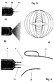
- FIG. 3a A particularly suitable flat jet nozzle in the form of a Taylor injector is shown in Figures 3a to 3c shown.
- Figures 3a and b show cross sections through a flat jet nozzle in two perpendicular cross-sectional planes.
- the cross section through the nozzle 9 is in the direction of the nozzle outlet opening 11 tapering tapered inner contour 12.
- the same nozzle 9 points in a second cross-sectional plane, which is perpendicular is to the cross-sectional plane shown in Figure 3a, one in the direction of Cross-sectional contour that widens in a conical shape.
- FIG 4 is a flat jet nozzle 9 in front of the air inlet slot 3 of a burner shown.
- the air inlet slot 3 is limited by the walls of the partial cone body 1 and 2.
- the flat spray nozzle 9 on both sides above and below the fan-shaped fuel / air mixture each have a protective cover 13.
Abstract
Description
Die vorliegende Erfindung betrifft ein Verfahren zur Verbrennung von flüssigen
Brennstoffen in einem Brenner gemäss Oberbegriff des Anspruchs 1. Sie betrifft
auch einen Brenner zur Anwendung des Verfahrens.The present invention relates to a method for the combustion of liquid
Fuels in a burner according to the preamble of
Ein Brenner der vorstehend genannten Gattung geht beispielsweise aus der EP 0321 809 B1 hervor und wird mit großem Erfolg zur Befeuerung von Gasturbinenanlagen eingesetzt. Diese Brennerart gilt als erfolgreicher Ausgangstyp von Brennern, die zur Befeuerung mit hochreaktiven, gasförmigen und flüssigen Brennstoffen mit einem hohen Heizwert von etwa 35 bis 50 MJ/kg ausgelegt worden sind. Hirbei wird der flüssige Brennstoff in das Innere der Brennkammer mittels einer mittig zum Kegelhohlraum angebrachten Düsenanordnung in Form eines sich kegelförmig ausbildenden Brennstoffsprays eingebracht. Das kegelförmige Brennstoffspray wird von einem tangential in den Kegelhohlraum einströmenden rotierenden Verbrennungsluftstrom umschlossen und dadurch stabilisiert. Erst im Bereich des Wirbelaufplatzens, also im Bereich der sogenannten Rückströmzone, wird die optimale, homogene Brennstoffkonzentration über den Querschnitt erreicht, so daß in diesem Bereich die Zündung des Brennstoffgemisches erfolgt. Gasförmiger Brennstoff wird aus zwei den Lufteintrittsschlitzen des Brenners entlang verlaufenden Gaszufuhrrohren durch Bohrungsreihen quer zur Lufteintrittsströmung eingedüst.A burner of the type mentioned above goes for example from the EP 0321 809 B1 and is used with great success for firing gas turbine systems used. This type of burner is considered a successful type of burner output, those for firing with highly reactive, gaseous and liquid fuels designed with a high calorific value of around 35 to 50 MJ / kg are. Hirbei is using the liquid fuel inside the combustion chamber a nozzle arrangement in the center of the cone cavity in the form of a introduced conical fuel sprays. The conical Fuel spray is from a tangent flowing into the cone cavity rotating combustion air flow enclosed and thereby stabilized. Only in Area of the vortex runout, i.e. in the area of the so-called backflow zone the optimal, homogeneous fuel concentration is achieved across the cross-section, so that the ignition of the fuel mixture takes place in this area. Gaseous fuel is created from two along the burner's air inlet slots running gas supply pipes through rows of holes transverse to the air inlet flow injected.
Die durch die Doppelkegelstruktur vorgegebene innere und äußere Form des Brenners kann als Endprodukt eines umfangreichen Optimierungsprozesses angesehen werden, bei dem der Brenner unter dem Gesichtspunkt der Verbrennung flüssiger Brennstoffes mit hohem Heizwert optimiert worden ist.The inner and outer shape of the Brenners can be seen as the end product of an extensive optimization process in which the burner from the point of view of combustion liquid fuel with a high calorific value has been optimized.
Die bestehende Technik für hochkalorische gasförmige Brennstoffe führt zu sehr
niedrigen Stickoxid-Emissionen bei ![]()
![]()
Der Erfindung, wie sie in den Ansprüchen gekennzeichnet ist, liegt die Aufgabe zugrunde, bei einem Verfahren sowie einem Brenner der eingangs genannten Art die Eindüsungstechnik eines bestehenden Brenners für flüssige Brennstoffe dahingehend zu erweitern, dass sehr niedrige Nox-Emissionen auch ohne zusätzliche Eindüsung von Wasser oder Dampf erreicht werden können.The invention, as characterized in the claims, is the object based on a method and a burner of the type mentioned the injection technology of an existing burner for liquid fuels expand that very low NOx emissions even without additional Injection of water or steam can be achieved.
Die Zielsetzungen der Erfindung sind also:
Insbesondere soll der Brenner zur Erfüllung der obenstehenden Ziele nicht in seiner Grundstruktur verändert werden, da der Brenner für die Verbrennung hochkalorischer Brennstoffe optimiert ist. Abweichungen von der optimierten Brennerform würden unmittelbar zu Verschlechterungen bei der Verbrennung hochkalorischer Brennstoffe führen.In particular, the burner should not be used to meet the above objectives Basic structure to be changed because the burner for the combustion of high calorific Fuels is optimized. Deviations from the optimized torch shape would immediately lead to deterioration in the combustion of high calorific Lead fuels.
Die Lösung der der Erfindung zugrundeliegenden Aufgabe ist im Anspruch 1 angegeben,
in dem ein erfindungsgemäßes Verfahren beschrieben ist. Ein nach dem
Verfahren arbeitender erfindungsgemäßer Brenner ist Gegenstand des Anspruchs
3. Ebenso ist ein verallgemeinerter Brenner, der erfindungsgemäß ausgebildet ist,
Gegenstand des Anspruchs 13. Den Erfindungsgedanken vorteilhaft weiterbildende
Merkmale sind Gegenstand der Unteransprüche.The solution to the problem on which the invention is based is specified in
Der Erfindung liegt die Idee zugrunde, zur Verbrennung von flüssigen Brennstoffen
in einen Brenner, der wenigstens zwei halbe, hohle Teilkegelkörper aufweist,
die einen kegelförmigen Hohlraum einschließen und deren Längssymmetrieachsen
zueinander versetzt verlaufen, wodurch mindestens zwei tangentiale Lufteintrittsschlitze
für einen Verbrennungszuluftstrom entstehen, zusammen mit dem
Verbrennungszuluftstrom einen flächenartig aufgefächerten Sprühnebel eines
Brennstoff-/Luft-Gemisches in die Lufteintrittsschlitze einzubringen.
Die ebene Brennstoff-/Luft-Gemisch-Strömung ist mittig jeweils zu den Lufteintrittsschlitzen
auszurichten, so daß der in kleinste Tröpfchen zerstäubte Brennstoff
nicht an die Innenwandung der die Lufteintrittsschlitze einschließenden Teilkegelkörper
gelangt. The invention is based on the idea of burning liquid fuels in a burner which has at least two half, hollow partial cone bodies which enclose a conical cavity and whose axes of longitudinal symmetry are offset with respect to one another, as a result of which at least two tangential air inlet slots for a combustion supply air flow, together with the Combustion supply air flow to introduce a spray of a fuel / air mixture fanned out in the form of a surface into the air inlet slots.
The flat fuel / air mixture flow is to be aligned centrally to the air inlet slots, so that the fuel atomized into the smallest droplets does not reach the inner wall of the partial cone body enclosing the air inlet slots.
Zur Eindüsung und Erzeugung eines flächenartigen Sprühnebels ist vor den jeweiligen Lufteintrittsschlitzen eine Eindüsungsvorrichtung angebracht, die wenigstens eine, vorzugsweise zwei oder drei Fächerstrahldüsen aufweist. Die als Taylor-Injektoren ausgebildeten Fächerstrahldüsen werden typischerweise zur Brennstoffzerstäubung mit einem Brennstoffdruck von ca. 100 bar betrieben, wodurch Brennstofftröpfchen mit einem Durchmesser zwischen etwa 1 und 100 µm, vorzugsweise 10 bis 30 µm entstehen.For the injection and generation of a flat spray is in front of the respective Air inlet slots attached an injection device, at least has one, preferably two or three fan jet nozzles. The as Taylor injectors trained fan jet nozzles are typically used for atomizing fuel operated with a fuel pressure of approx. 100 bar, whereby Fuel droplets with a diameter between about 1 and 100 microns, preferably 10 to 30 µm arise.
Die Tröpfchengröße der zerstäubten Brennstofftröpfchen spielt insofern eine wichtige Rolle, da die in die Lufteintrittsschlitze eingebrachten Brennstofftröpfchen nicht unmittelbar bei Eintritt in die Brennerstruktur aufgrund der vorherrschenden, hohen Temperaturen entzündet werden sollen, sondern vielmehr auf dem Weg zwischen den Lufteintrittsschlitzen und dem Bereich innerhalb des Brenners, in dem der Zündbereich vorgesehen ist, mit der Verbrennungszuluft vermischt werden und darüber hinaus verdampfen sollen, bevor das Brennstoff/Luft-Gemisch die Reaktionszone erreicht. Insofern ist die Tröpfchengröße der in die Lufteintrittsschlitze einzudüsenden Brennstofftröpfchen nach Maßgabe der Wegstrecke zu wählen, die durch die Brennergeometrie vorgegeben ist. Durch geeignetes Einstellen der Tröpfchengröße kann somit die Rückzündgefahr in den Bereich der Brennstoffeindüsung vermieden werden.The droplet size of the atomized fuel droplets therefore plays an important role Role because the fuel droplets introduced into the air inlet slots not immediately upon entering the burner structure due to the prevailing high temperatures should be ignited, but rather on the way between the air inlet slots and the area inside the burner, in which the ignition area is provided, with which combustion air is mixed and should also evaporate before the fuel / air mixture reached the reaction zone. In this respect, the droplet size is that in the air inlet slots droplets of fuel to be injected according to the distance select that is specified by the burner geometry. By appropriate adjustment the droplet size can thus reduce the risk of reignition in the range of Fuel injection can be avoided.
Zur Eindüsung des Brennstoffes in die Lufteinrittsschlitze eignen sich als Eindüsungsvorrichtung besonders Fächerstrahldüsen in Form von Taylor-Injektoren, die eine im Düsenauslaßbereich geeignete Innenkontur aufweisen, wodurch ein ebener Brennstoffstrahl entsteht. Grundsätzlich kann ein ebener Flüssigkeitsstrahl dadurch erzeugt werden, indem zwei Flüssigkeitsstrahlen unter einem Winkel aufeinander treffen, wodurch sich ein abgeflachter, vorzugsweise in einer Ebene ausbreitender Flüssigkeitsstrahl ergibt. Besondere Ausführungsformen derartiger, sogenannter Flachstrahldüsen werden unter Bezugnahme auf die nachstehenden Zeichnungen näher beschrieben. To inject the fuel into the air inlet slots are suitable as an injection device especially fan jet nozzles in the form of Taylor injectors, which have a suitable inner contour in the nozzle outlet area, whereby a flat fuel jet is created. Basically, a flat jet of liquid thereby generated by two liquid jets at an angle to each other meet, whereby a flattened, preferably spreading in a plane Liquid jet results. Special embodiments of such, so-called Flat fan nozzles are described with reference to the following Drawings described in more detail.
Die Erfindung wird nachstehend ohne Beschränkung des allgemeinen Erfindungsgedankens anhand eines Ausführungsbeispielen unter Bezugnahme auf die Zeichnungen exemplarisch beschrieben. Es zeigen:
- Fig. 1
- Seitendarstellung eines Brenners mit längs zum Lufteintrittsschlitz angebrachter Eindüsungsvorrichtung,
- Fig. 2a,b,c
- Eindüsungsvarianten des zweidimensionalen Brennstoff-/Luft-Gemisches in einen Lufteintrittsschlitz,
- Fig. 3a,b,c
- schematische Darstellung einer Flachstrahldüse, sowie
- Fig. 4
- Querschnittsdarstellung durch eine vor einem Lufteintrittsschlitz angebrachte Flachstrahldüse mit Schutzblende.
- Fig. 1
- Side view of a burner with an injection device arranged lengthways to the air inlet slot,
- 2a, b, c
- Injection variants of the two-dimensional fuel / air mixture into an air inlet slot,
- 3a, b, c
- schematic representation of a flat jet nozzle, and
- Fig. 4
- Cross-sectional representation through a flat jet nozzle with a protective screen attached in front of an air inlet slot.
Figur 1 zeigt einen Brenner in Seitensichtdarstellung, der im wesentlichen aus
zwei halben, hohlen Teilkegelkörper 1, 2 zusammengesetzt ist, die jeweils zwei
Lufteintrittsschlitze begrenzen, von denen ein Lufteintrittsschlitz 3 in Figur 1 zu
sehen ist. Ein solcher Brenner ist aus EP-0 321 809 B1 bekanntgeworden, wobei
diese Druckschrift einen integrierenden Bestandteil vorliegender Beschreibung
bildet. Vor dem Lufteintrittsschlitz ist eine Eindüsungsvorrichtung 4 vorgesehen,
die über einen Verbindungssteg 5 abnehmbar fest mit einer Basisplatte 6 des
Brenners verbunden ist. Die in der Figur 1 dargestellte Eindüsungsvorrichtung 4 ist
über einen ringförmig ausgebildeten Rahmen 7 mit der hinteren, nicht im einzelnen
dargestellten Eindüsungsvorrichtung 8 verbunden.Figure 1 shows a burner in a side view, which consists essentially of
two half, hollow
Jede Eindüsungsvorrichtung (siehe 4) erstreckt sich über die gesamte Länge des
Lufteintrittsschlitzes 3 und sieht Flachstrahldüsen 9 vor. Die Flachstrahldüsen 9
zerstäuben den durch die Eindüsungsvorrichtung 4 zugeführten Brennstoff jeweils
in Form eines ebenen Sprühnebels 10 bzw. eines sich fächerförmig ausbreitenden
Brennstoff-/Luft-Gemisches derart, daß das Brennstoff-/Luft-Gemisch mittig in den
Lufteintrittsschlitz 4 einmündet.Each injection device (see FIG. 4) extends over the entire length of the
Die aus den beiden Flachstrahldüsen 9 austretenden Brennstoffstrahlen sind derart
zueinander orientiert, daß sie vor Eintritt in den Lufteintrittsschlitz 3 die gesamte
Länge des Schlitzes mit einem zusammenhängenden Brennstoff-/Luft-Gemisch
abdecken, wodurch der Brenner gleichmäßig und in homogener Verteilung
mit einem Brennstoff-/Luft-Gemisch versorgt wird.The fuel jets emerging from the two
In Figur 2a weist die Eindüsungsvorrichtung 4 im Unterschied zur Figur 1 sowie zu
Figur 2b drei Flachstrahldüsen 9 auf, deren Austrittsstrahlen 10 zusammen genommen
den gesamten Bereich des Lufteintrittsschlitzes 3 mit einem gleichmäßig
verteilten Brennstoff-/Luft-Gemisch überdecken.In Figure 2a, the
In Figur 2c ist die Eindüsungsvorrichtung 4 als eine einzige Flachstrahldüse ausgebildet,
die seitlich am Rande des Lufteintrittsschlitzes 3 angebracht ist. Die in
Figur 2c dargestellte Flachstrahldüse 9 richtet ihren Ausgangsstrahl schräg streifend
über die gesamte Erstreckung des Lufteintrittsschlitzes 3, so daß auch in diesem
Fall dafür gesorgt ist, daß der gesamte Bereich des Lufteintrittsschlitzes mit
dem Brennstoff-/Luft-Gemisch versorgt wird.2c, the
In allen vorstehend gezeigten Ausführungsbeispielen ist insbesondere dafür Sorge
zu tragen, daß das in dem Lufteintrittsschlitz 3 eingedüste Brennstoff-/Luft-Gemisch
nicht unmittelbar an die Innenwandung der Teilkegelkörper gelangt.In all of the exemplary embodiments shown above, this is particularly important
to bear that the fuel / air mixture injected into the
Eine besonders geeignete Flachstrahldüse in Form eines Taylor-Injektors ist in
den Figuren 3a bis 3c dargestellt. Die Figuren 3a und b zeigen Querschnitte durch
eine Flachstrahldüse in je zwei senkrecht zueinander stehenden Querschnittsebenen.
In Figur 3a weist der Querschnitt durch die Düse 9 eine in Richtung der Düsenauslaßöffnung
11 verjüngend kegelförmig verlaufende Innenkontur 12 auf.
Hingegen weist die gleiche Düse 9 in einer zweiten Querschnittsebene, die senkrecht
zu der in Figur 3a gezeigten Querschnittsebene steht, ein in Richtung der
Düsenöffnung kegelförmig erweiternde Querschnittskontur auf.A particularly suitable flat jet nozzle in the form of a Taylor injector is shown in
Figures 3a to 3c shown. Figures 3a and b show cross sections through
a flat jet nozzle in two perpendicular cross-sectional planes.
In FIG. 3a, the cross section through the
In Figur 3c sind in überlagernder Darstellung die einzelnen Querschnitte durch die Düsenöffnung gezeigt. Mit Hilfe derartig strukturierten Flachstrahldüse ist es möglich, ein zweidimensionales Flüssigkeits-/Luft-Gemisch zu erzeugen. Die Einstellung der sich durch die Zerstäubung der Düse der Flüssigkeit einstellenden Tröpfchengröße kann durch die Querschnittsgeometrie sowie durch den Vordruck, mit der die Flüssigkeit im Inneren durch die Düsenöffnung getrieben wird, individuell eingestellt werden.In Figure 3c, the individual cross-sections are shown in a superimposed representation Nozzle opening shown. With the help of such structured flat jet nozzle it is possible to create a two-dimensional liquid / air mixture. The setting the droplet size resulting from the atomization of the liquid nozzle can by the cross-sectional geometry and by the form, with which drives the liquid inside through the nozzle opening, individually can be set.
In Figur 4 ist eine Flachstrahldüse 9 vor dem Lufteintrittsschlitz 3 eines Brenners
dargestellt. Der Lufteintrittsschlitz 3 ist begrenzt durch die Wandungen der Teilkegelkörper
1 und 2. Zur Vermeidung seitlicher Sprüheffekte weist die Flachstrahldüse
9 beidseitig oberhalb und unterhalb zum fächerförmig ausgebildeten Brennstoff-/Luft-Gemisch
jeweils eine Schutzblende 13 auf.In Figure 4 is a
Durch die erfindungsgemäße Maßnahme der modulartig ausgebildeten, zusätzlich an einen Brenner anbringbare Einspritzvorrichtung können bestehende Brenner, die hinsichtlich der Verbrennung hochkalorischer gasförmiger Brennstoffe optimiert worden sind, zusätzlich auch mit flüssigen Brennstoffen ohne zusätzliche Wasser- oder Dampfeinspritzung bei niedrigen Stickoxid-Emissionen betrieben werden. Kostenintensive Umrüstmaßnahmen am Brenner selbst entfallen vollständig.Through the measure according to the invention of the modular design, in addition existing burners can be attached to a burner. optimized for the combustion of high calorific gaseous fuels have also been used with liquid fuels without additional Water or steam injection operated with low nitrogen oxide emissions become. Costly retrofitting measures on the burner itself are completely eliminated.
- 11
- halber, hohler Teilkegelkörperhalf, hollow partial cone body
- 22nd
- halber, hohler Teilkegelkörperhalf, hollow partial cone body
- 33rd
- LufteintrittsschlitzAir inlet slot
- 44th
- Eindüsungsvorrichtung Injection device
- 55
- VerbindungsstegConnecting bridge
- 66
- BasisplatteBase plate
- 77
- Rahmenframe
- 88th
- EindüsungsvorrichtungInjection device
- 99
- FlachstrahldüseFlat jet nozzle
- 1010th
- BrennstoffstrahlFuel jet
- 1111
- DüsenauslaßöffnungNozzle outlet opening
- 1212th
- verjüngend verlaufende Innenkonturtapering inner contour
- 1313
- SchutzblendeProtective cover
Claims (13)
Priority Applications (1)
| Application Number | Priority Date | Filing Date | Title |
|---|---|---|---|
| EP98810815A EP0981019A1 (en) | 1998-08-20 | 1998-08-20 | Method and burner for combustion of liquid fuels |
Applications Claiming Priority (1)
| Application Number | Priority Date | Filing Date | Title |
|---|---|---|---|
| EP98810815A EP0981019A1 (en) | 1998-08-20 | 1998-08-20 | Method and burner for combustion of liquid fuels |
Publications (1)
| Publication Number | Publication Date |
|---|---|
| EP0981019A1 true EP0981019A1 (en) | 2000-02-23 |
Family
ID=8236268
Family Applications (1)
| Application Number | Title | Priority Date | Filing Date |
|---|---|---|---|
| EP98810815A Withdrawn EP0981019A1 (en) | 1998-08-20 | 1998-08-20 | Method and burner for combustion of liquid fuels |
Country Status (1)
| Country | Link |
|---|---|
| EP (1) | EP0981019A1 (en) |
Cited By (3)
| Publication number | Priority date | Publication date | Assignee | Title |
|---|---|---|---|---|
| WO2002090831A1 (en) * | 2001-05-10 | 2002-11-14 | Institut Francais Du Petrole | Device and method for injecting a liquid fuel in an air flow for a combustion chamber |
| WO2003098110A1 (en) * | 2002-05-16 | 2003-11-27 | Alstom Technology Ltd | Premix burner |
| WO2005095858A1 (en) * | 2004-03-31 | 2005-10-13 | Alstom Technology Ltd | Method for spraying liquid fuel in a premix burner, and premix burner |
Citations (5)
| Publication number | Priority date | Publication date | Assignee | Title |
|---|---|---|---|---|
| US2117388A (en) * | 1935-04-30 | 1938-05-17 | Hammel Oil Burning Equipment C | Oil burner |
| EP0321809A1 (en) | 1987-12-21 | 1989-06-28 | BBC Brown Boveri AG | Process for combustion of liquid fuel in a burner |
| EP0433789A1 (en) * | 1989-12-19 | 1991-06-26 | Asea Brown Boveri Ag | Method for a premix burning of a liquid fuel |
| WO1995016881A1 (en) * | 1993-12-17 | 1995-06-22 | Abb Stal Ab | Method and apparatus for atomizing liquid fuel |
| DE4445279A1 (en) * | 1994-12-19 | 1996-06-20 | Abb Management Ag | Injector |
-
1998
- 1998-08-20 EP EP98810815A patent/EP0981019A1/en not_active Withdrawn
Patent Citations (5)
| Publication number | Priority date | Publication date | Assignee | Title |
|---|---|---|---|---|
| US2117388A (en) * | 1935-04-30 | 1938-05-17 | Hammel Oil Burning Equipment C | Oil burner |
| EP0321809A1 (en) | 1987-12-21 | 1989-06-28 | BBC Brown Boveri AG | Process for combustion of liquid fuel in a burner |
| EP0433789A1 (en) * | 1989-12-19 | 1991-06-26 | Asea Brown Boveri Ag | Method for a premix burning of a liquid fuel |
| WO1995016881A1 (en) * | 1993-12-17 | 1995-06-22 | Abb Stal Ab | Method and apparatus for atomizing liquid fuel |
| DE4445279A1 (en) * | 1994-12-19 | 1996-06-20 | Abb Management Ag | Injector |
Cited By (7)
| Publication number | Priority date | Publication date | Assignee | Title |
|---|---|---|---|---|
| WO2002090831A1 (en) * | 2001-05-10 | 2002-11-14 | Institut Francais Du Petrole | Device and method for injecting a liquid fuel in an air flow for a combustion chamber |
| FR2824625A1 (en) * | 2001-05-10 | 2002-11-15 | Inst Francais Du Petrole | DEVICE AND METHOD FOR INJECTING A LIQUID FUEL INTO AN AIRFLOW FOR A COMBUSTION CHAMBER |
| US7249721B2 (en) | 2001-05-10 | 2007-07-31 | Institut Francais Du Petrole | Device and method for injecting a liquid fuel into an air flow for a combustion chamber |
| WO2003098110A1 (en) * | 2002-05-16 | 2003-11-27 | Alstom Technology Ltd | Premix burner |
| US7013648B2 (en) | 2002-05-16 | 2006-03-21 | Alstom Technology Ltd. | Premix burner |
| WO2005095858A1 (en) * | 2004-03-31 | 2005-10-13 | Alstom Technology Ltd | Method for spraying liquid fuel in a premix burner, and premix burner |
| DE102004015904A1 (en) * | 2004-03-31 | 2005-10-20 | Alstom Technology Ltd Baden | Method of liquid fuel atomization in a premix burner and premix burner |
Similar Documents
| Publication | Publication Date | Title |
|---|---|---|
| EP1802915B1 (en) | Gas turbine burner | |
| DE19536837B4 (en) | Apparatus and method for injecting fuels into compressed gaseous media | |
| EP0794383B1 (en) | Method of operating a pressurised atomising nozzle | |
| EP0503319B1 (en) | Burner for a premixing combustion of a liquid and/or a gaseous fuel | |
| EP0892212B1 (en) | Pressure spray nozzle | |
| EP0902233A1 (en) | Combined pressurised atomising nozzle | |
| DE2834313A1 (en) | FUEL NOZZLE | |
| EP0711953B1 (en) | Premix burner | |
| EP0598189A1 (en) | Pulverizer for an oil burner | |
| DE3609960A1 (en) | DEVICE AND METHOD FOR SPRAYING LIQUID FUEL | |
| EP0924460B1 (en) | Two-stage pressurised atomising nozzle | |
| EP0718550B1 (en) | Injection nozzle | |
| EP0908671B1 (en) | Combustion process for gaseous, liquid fuels and fuels having medium or low calorific value in a burner | |
| EP0742411B1 (en) | Air supply for a premix combustor | |
| EP0924461B1 (en) | Two-stage pressurised atomising nozzle | |
| EP0911582B1 (en) | Method for operating a premix burner and premix burner | |
| EP0924459A1 (en) | Method and apparatus for injecting a mixture of fuel end liquid into a combustor | |
| DE4215763A1 (en) | burner | |
| CH682009A5 (en) | ||
| EP0981019A1 (en) | Method and burner for combustion of liquid fuels | |
| EP0777082A2 (en) | Premix burner | |
| DE3943096A1 (en) | Atomiser for liquid fuel - has inner and outer chambers with primary and secondary nozzles | |
| DE19537636A1 (en) | Power generation method for power station | |
| EP0496016A1 (en) | High pressure spray nozzle | |
| EP0981016A1 (en) | Burner and method for operating an internal combustion engine |
Legal Events
| Date | Code | Title | Description |
|---|---|---|---|
| PUAI | Public reference made under article 153(3) epc to a published international application that has entered the european phase |
Free format text: ORIGINAL CODE: 0009012 |
|
| AK | Designated contracting states |
Kind code of ref document: A1 Designated state(s): AT BE CH CY DE DK ES FI FR GB GR IE IT LI LU MC NL PT SE |
|
| AX | Request for extension of the european patent |
Free format text: AL;LT;LV;MK;RO;SI |
|
| AKX | Designation fees paid | ||
| STAA | Information on the status of an ep patent application or granted ep patent |
Free format text: STATUS: THE APPLICATION IS DEEMED TO BE WITHDRAWN |
|
| 18D | Application deemed to be withdrawn |
Effective date: 20000824 |
|
| REG | Reference to a national code |
Ref country code: DE Ref legal event code: 8566 |