EP1124400A2 - Handoff system for wireless communications - Google Patents
Handoff system for wireless communications Download PDFInfo
- Publication number
- EP1124400A2 EP1124400A2 EP01300745A EP01300745A EP1124400A2 EP 1124400 A2 EP1124400 A2 EP 1124400A2 EP 01300745 A EP01300745 A EP 01300745A EP 01300745 A EP01300745 A EP 01300745A EP 1124400 A2 EP1124400 A2 EP 1124400A2
- Authority
- EP
- European Patent Office
- Prior art keywords
- base station
- wireless terminal
- request
- handoff
- base
- Prior art date
- Legal status (The legal status is an assumption and is not a legal conclusion. Google has not performed a legal analysis and makes no representation as to the accuracy of the status listed.)
- Granted
Links
- 238000004891 communication Methods 0.000 title claims description 31
- 238000000034 method Methods 0.000 claims abstract description 34
- 230000004044 response Effects 0.000 claims abstract description 11
- 230000008569 process Effects 0.000 abstract description 27
- 238000012360 testing method Methods 0.000 description 13
- 230000006870 function Effects 0.000 description 10
- 210000004027 cell Anatomy 0.000 description 7
- 238000010586 diagram Methods 0.000 description 3
- 238000010276 construction Methods 0.000 description 2
- 238000005259 measurement Methods 0.000 description 2
- 238000010200 validation analysis Methods 0.000 description 2
- 210000004460 N cell Anatomy 0.000 description 1
- 238000009434 installation Methods 0.000 description 1
- 230000003993 interaction Effects 0.000 description 1
- 238000012546 transfer Methods 0.000 description 1
- 230000007704 transition Effects 0.000 description 1
Images
Classifications
-
- H—ELECTRICITY
- H04—ELECTRIC COMMUNICATION TECHNIQUE
- H04W—WIRELESS COMMUNICATION NETWORKS
- H04W36/00—Hand-off or reselection arrangements
- H04W36/0005—Control or signalling for completing the hand-off
- H04W36/0055—Transmission or use of information for re-establishing the radio link
- H04W36/0061—Transmission or use of information for re-establishing the radio link of neighbour cell information
-
- H—ELECTRICITY
- H04—ELECTRIC COMMUNICATION TECHNIQUE
- H04W—WIRELESS COMMUNICATION NETWORKS
- H04W12/00—Security arrangements; Authentication; Protecting privacy or anonymity
- H04W12/06—Authentication
- H04W12/062—Pre-authentication
-
- H—ELECTRICITY
- H04—ELECTRIC COMMUNICATION TECHNIQUE
- H04W—WIRELESS COMMUNICATION NETWORKS
- H04W36/00—Hand-off or reselection arrangements
- H04W36/08—Reselecting an access point
-
- H—ELECTRICITY
- H04—ELECTRIC COMMUNICATION TECHNIQUE
- H04W—WIRELESS COMMUNICATION NETWORKS
- H04W8/00—Network data management
- H04W8/005—Discovery of network devices, e.g. terminals
-
- H—ELECTRICITY
- H04—ELECTRIC COMMUNICATION TECHNIQUE
- H04W—WIRELESS COMMUNICATION NETWORKS
- H04W92/00—Interfaces specially adapted for wireless communication networks
- H04W92/16—Interfaces between hierarchically similar devices
- H04W92/20—Interfaces between hierarchically similar devices between access points
Definitions
- This invention relates to the art of wireless communication, and more particularly, to a system of handing off communications with a wireless terminal from one base station to another.
- Prior art wireless systems have a central controller which determines which base station communicates with a wireless terminal and facilitates transferring, or so-called "handing off', of communication between the wireless terminal from a first base station to a second base station when it is determined that a better communications link can be maintained between the second base station and the wireless terminal than between the first base station and the wireless terminal.
- the wireless terminal may assist in the handoff process by providing signal strength measurements to the central controller, while the central controller has ultimate control of the handoff process.
- prior art wireless systems that support mobile terminals need to know à priori, such as upon initial system installation, or reinstallation, e.g., upon adding to or removing from the system a base station, the "map" of the base stations.
- This map includes information about at least which base stations are neighbors, and may also include the frequencies and/or timing parameters used by the various base stations and other such configuration information, depending on the nature of the air interface, i.e., the wireless links between the wireless terminals and the base stations, employed in the system.
- information is provided at a high cost by system engineering or planning before constructing the network.
- a wireless terminal controlled handoff process by which at least portions of the map of the base stations is discovered and updated.
- the portion of the map that is discovered by a particular base station is typically its neighbors to which it can possibly hand off a call it is serving. It takes at least one handoff with each such base station neighbor for the particular base station to discover its entire local map, i.e., the map information for all the base stations that surround the particular base station and to which the particular base station can perform handoffs.
- the wireless terminal handoff process is used to supply a base station with information about other base stations with whom the base station can cooperate to perform handoffs.
- the handoff process may subsequently be performed more expeditiously between the particular base station and such other base stations. Further advantageously, the costs associated with the à priori system engineering are avoided.
- the wireless terminal tells the new base station to which it is handing off the call the identity of the previous base station from which control is being handed off. The wireless terminal then completes the handoff and begins to be served by the new base station. If the new base station does not have a valid record for the previous base station, it forms a trust relationship with the previous base station and creates a record for it, thus identifying it as a neighbor to which it can perform expedited handoff in response to the control of a wireless terminal.
- processors may be provided through the use of dedicated hardware as well as hardware capable of executing software in association with appropriate software.
- the functions may be provided by a single dedicated processor, by a single shared processor, or by a plurality of individual processors, some of which may be shared.
- explicit use of the term "processor” or “controller” should not be construed to refer exclusively to hardware capable of executing software, and may implicitly include, without limitation, digital signal processor (DSP) hardware, read-only memory (ROM) for storing software, random access memory (RAM), and non-volatile storage. Other hardware, conventional and/or custom, may also be included.
- DSP digital signal processor
- ROM read-only memory
- RAM random access memory
- non-volatile storage non-volatile storage
- any switches shown in the FIGS. are conceptual only. Their function may be carried out through the operation of program logic, through dedicated logic, through the interaction of program control and dedicated logic, or even manually, the particular technique being selectable by the implementor as more specifically understood from the context.
- any element expressed as a means for performing a specified function is intended to encompass any way of performing that function including, for example, a) a combination of circuit elements which performs that function or b) software in any form, including, therefore, firmware, microcode or the like, combined with appropriate circuitry for executing that software to perform the function.
- the invention as defined by such claims resides in the fact that the functionalities provided by the various recited means are combined and brought together in the manner which the claims call for.
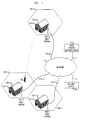
- FIG. 1 shows an exemplary network arrangement in accordance with the principles of the invention. Shown in FIG. 1 are a) wireless terminal 101; b) N base stations 103, where N is an integer greater than or equal to 2, including base station 103-1 through 103-N; c) N antennas 105, including antennas 105-1 through 105-N; d) N structures 107, including structures 107-1 through 107-N; e) N cells 109, including cells 109-1 through 109-N; f) network 111; g) base station authentication unit 113; h) N communication links 115, including communication links 115-1 through 115-N; i) communication links 117 and 121; j) security center 119.
- Wireless terminal 101 is able to communicate with multiple base stations which transmit with sufficient signal strength to be detected and useable for communication at the current location of wireless terminal 101. Once a signal of sufficient strength is detected for a particular base station, wireless terminal 101 may engage in communication with that base station.
- the particular types of wireless link and protocol, i.e., the air interface, employed by wireless terminal 101 are not essential to the invention and may be any type desired by the implementor, although of course the radio link and protocol employed by wireless terminal 101 must be the same type employed by base stations 103.
- Wireless terminal 101 may achieve communication with multiple base stations in any manner desired by the implementer.
- wireless terminal 101 may have only a single receiver, and it may receive signals, when not occupied with the exchange of information with the base station currently serving it, from other base stations that have signals of sufficient strength reaching wireless terminal 101.
- wireless terminal 101 may receive signals from multiple base stations simultaneously, e.g., by employing multiple parallel receivers in wireless terminal 101.
- wireless terminal 101 may have more than one receiver, but the number of receivers is less than the number of base stations from which wireless terminal 101 can receive a signal of sufficient strength at its current location, so wireless terminal 101 needs to perform scanning on at least one of its receivers to obtain signals for some of the base stations.
- Base stations 103 are substantially conventional base stations except for the following. First, base stations 103 need not be connected to a dedicated network for inter-base-station communication. Instead, base stations 103 can employ a shared public network, e.g., an internet protocol (IP)-based network such as the Internet. Second, each base station 103 need not contain any "map" information. Instead, each of base stations 103 is capable of discovering its necessary portions of the "map" information, in accordance with the principles of the invention. Preferably, base stations 103 are small base stations that can easily be incorporated into a small space, e.g., one that is already available, rather than requiring dedicated construction and site preparation.
- IP internet protocol
- such small size coupled with the ability to discover the necessary portions of the "map" information, enable the rapid construction of a new wireless communication network.
- a wireless communication network is flexible in its architecture, i.e., base stations can easily be added or removed, and it is also easy to maintain.
- Each of antennas 105 are coupled to a respective one of base stations 103. Each of antennas 105 radiates the signal developed by its respective one of base stations 103. Each combination of a one of base stations 103 and its respective one of antennas 105 yields a one of cells 109, which is a particular coverage area.
- the shape of cells 109 in FIG. 1 do not represent actual cell shapes but instead are merely conventional notation for cells. Note that the shape of the actual various cells 109 are all independent.
- Each of structures 107 provides a facility in which to place one or more of base stations 103. Furthermore, structures 107 may also provide a place on which to mount antennas 105. For example, some of structures 107 may be already existing homes in which a one of base stations 103 is located in an unused space and to which a one of antennas 105 is exteriorly affixed.
- Network 111 provides a way for base stations 103 to communicate with each other, as well as with base station authentication unit 113 and security center 119.
- Network 111 may be made up of various subnetworks, which may be networks in their own right. Furthermore, the various subnetworks may be of different types and may employ different protocols.
- network 111 is a packet based network, e.g., an asynchronous transfer mode (ATM) network or an IP network.
- ATM asynchronous transfer mode
- Each of base stations 103 is connected to network 111 via a respective one of communication links 115, which may be construed as part of network 111.
- network 111 or at least a subnetwork thereof, is an IP network
- communications link 115 may be an Internet connection, e.g., over cable television lines or a fiber-to-the curb connection, that is shared by the base station for communicating with other base stations and by the occupants of the home for Internet browsing.
- Base station authentication unit 113 contains a list of all valid base stations 103, and any associated information such as security keys and alternative identifiers or addresses of the base station.
- a base station may be listed in base station authentication unit 113 at any point. However, the base station only becomes valid once it is listed in base station authentication unit 113.
- base station authentication unit 113 may be made up of several parts, which need not be geographically collocated. Furthermore, to improve reliability and performance, some or all of the various parts or functions of base station authentication unit 113 may be replicated, as will be readily recognized by those of ordinary skill in the art.
- Base station authentication unit 113 is connected to network 111 via communication link 117.
- communication link 117 is construed as covering all the necessary communications paths between network 111 and the various parts or replicas.
- Security center 119 contains a list of all valid wireless terminals that may be served.
- security center 119 contains security information, such as authentication challenge-response pairs and/or encryption keys associated with each wireless terminal. The security information may be distributed by security center 119 to base stations 103, as necessary.
- a wireless terminal may be listed in security center 119 at any point. However, the wireless terminal only becomes valid once it is listed in security center 119.
- security center 119 may be made up of several parts, which need not be geographically collocated. Furthermore, to improve reliability and performance, some or all of the various parts or functions of security center 119 may be replicated, as will be readily recognized by those of ordinary skill in the art.
- Security center 119 is connected to network 111 via communication link 121.
- communication link 121 is construed as covering all the necessary communications paths between network 111 and the various parts or replicas.
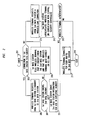
- FIG. 2 shows an exemplary process, in flow chart form, for performing a handoff of wireless terminal 101 between the base stations of FIG. 1, in accordance with the principles of the invention.
- a base station may discover and update at least portions of the "map".
- the portion of the map that is discovered by a particular base station, i.e., the base station's local map, is typically its neighbors to which it can possibly handoff a call it is serving. It takes at least one handoff with each such base station neighbor for the particular base station to discover its entire local map.
- step 201 When it is determined that a wireless terminal, e.g., wireless terminal 101 (FIG. 1), requires a handoff, because the signal of the radio link of the base station with which it is communicating, e.g., base station 103-1 of FIG. 1, has become sufficiently weaker than that of another particular base station, e.g., base station 103-2 of FIG. 1, so that it appears that the other particular base station could provide a better radio link.
- Next conditional branch point 203 (FIG. 2) tests to determine if the connection to the first base station, e.g., base station 103-1 of FIG.
- step 203 If the test result in step 203 is YES, indicating that that the connection continues to exist between the first base station and the wireless terminal, control passes to step 205, in which the wireless terminal requests a handoff from the first base station to the second base station, e.g., base station 103-2 of FIG. 1.
- the wireless terminal may send various measurements of the signal strengths as received at the wireless terminal for the first and second base stations to the first base station, which determines that it is an appropriate time for a handoff. The first base station therefore tells the wireless terminal to connect to the second base station.
- conditional branch point 207 tests to determine if the first base station "knows" the second base station, i.e., the first base station has the second base station listed in its "map" information, such a listing having been the result of a previous handoff of a wireless terminal between the first and second base stations. More specifically, as part of the listing in the map information, the first base station may know a) the base station identification of the second base station, b) the network address of the second base station, e.g., its IP address, and c) security information, such as the public key of the second base station, which is used to secure communication between the first and second base stations.
- step 207 If the test result in step 207 is NO, indicating the first base station does not "know” the second base station, control passes to step 209, in which the first base station tells the wireless terminal that it does not know the second base station and that the wireless terminal must arrange for a wireless link connection with the second base station on its own. This may be achieved, for example, by using the same process that a wireless terminal uses to establish an initial wireless link with a base station when it first powers up within the cell served by that base station, as described further hereinbelow.
- step 203 If the test result in step 203 is NO, indicating that the connection from the wireless terminal to the first base station had been terminated, or after step 209, control passes to step 211, in which the wireless terminal requests that the second base station establish with it a wireless link. In response to this request, the second base station attempts to authenticate the wireless terminal, which may require use of information stored in a security center, e.g., security center 119 of FIG. 1, in step 213. Thereafter, conditional branch point 215 tests to determine if the wireless terminal was successfully authenticated.
- a security center e.g., security center 119 of FIG.
- step 215 If the test result in step 215 is YES, indicating that the wireless terminal is allowed to utilize the base stations for communication, control passes to step 217, in which the wireless terminal is connected for carrying user traffic to the second base station. As part of this step, other portions of the network which were transmitting data to the wireless terminal via the first base station are instructed to now transmit their data to the wireless terminal via the second base station, e.g., using the techniques of the well known Mobile Internet Protocol. Thereafter, the process is exited in step 219.
- test result in step 215 is NO, indicating that the wireless terminal is not allowed to utilize the base stations for communication, control passes to step 219 and the process is exited.
- step 221 in which the first base station sends the second base station information to expedite the handoff process, in accordance with an aspect of the invention.
- expediting information may include a) an indication that it is OK to take the handoff, i.e., the wireless terminal is permitted to make use of the base stations, b) security information associated with the wireless terminal, such as authentication challenge-response pairs and/or encryption keys, and c) any data not yet sent by the first base station to the wireless terminal.
- control passes to step 217 and the process continues as described above.
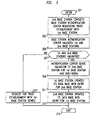
- FIG. 3 shows an exemplary process, in flow chart form, by which one base station gets to know about another base station that it does not currently have a valid entry for, and whose presence it became aware of by virtue of a recent need for a handoff by a wireless terminal.
- the process is entered in step 301 after there is a request for a nonexpedited handoff by a wireless terminal, e.g., at any point after execution of step 211 of FIG. 2.
- the second base station wants to know about the first base station.
- the second base station e.g. base station 103-2 of FIG. 1
- a base station authentication unit e.g., base station authentication unit 113 of FIG. 1
- the base station authentication unit looks up the first and second base stations in its list, and attempts to determine if they are who they say they are, e.g., using a challenge response process.
- Conditional branch point 307 tests to determine if both the first and second base stations are valid.
- step 307 If the test result in step 307 is YES, indicating that both the first and second base stations are valid, control passes to step 309, in which the base station authentication unit sends a validation message for the first base station to the second base station and for the second base station to the first base station.
- This message may also include additional information such as network addresses and security information.
- the first and second base stations may exchange such additional information among themselves.
- step 311 in response to receipt of the message regarding the second base station, the first base station updates its data base with an entry for the second base station, in accordance with an aspect of the invention. As a result, the first base station will now "know” the second base station and will be able to perform expedited handoffs with it.
- step 313 in response to receipt of the message regarding the first base station, the second base station updates its data base with an entry for the first base station, in accordance with the principles of the invention. As a result, the second base station will now "know” the first base station and will be able to perform expedited handoffs with it. Thereafter the process is exited in step 315.
- test result in step 307 is NO, indicating that at least one of the first and second base stations is not valid
- the process of FIG. 3 may be entered after step 207 (FIG. 2) when the test result in step 207 is NO.
- step 207 FIG. 2
- the roles of first base station and second base station are interchanged.
- the request for a handoff may not come from, or be controlled by, the wireless terminal. Instead, the request for a handoff, or the decision to perform the handoff, may be originated by a base station, typically using information obtained from the wireless terminal.
Abstract
Description
- This invention relates to the art of wireless communication, and more particularly, to a system of handing off communications with a wireless terminal from one base station to another.
- Prior art wireless systems have a central controller which determines which base station communicates with a wireless terminal and facilitates transferring, or so-called "handing off', of communication between the wireless terminal from a first base station to a second base station when it is determined that a better communications link can be maintained between the second base station and the wireless terminal than between the first base station and the wireless terminal. Typically, the wireless terminal may assist in the handoff process by providing signal strength measurements to the central controller, while the central controller has ultimate control of the handoff process.
- For the purposes of handoff, as well as other reasons, prior art wireless systems that support mobile terminals need to know à priori, such as upon initial system installation, or reinstallation, e.g., upon adding to or removing from the system a base station, the "map" of the base stations. This map includes information about at least which base stations are neighbors, and may also include the frequencies and/or timing parameters used by the various base stations and other such configuration information, depending on the nature of the air interface, i.e., the wireless links between the wireless terminals and the base stations, employed in the system. Typically such information is provided at a high cost by system engineering or planning before constructing the network.
- We have recognized that the cost of wireless systems can be reduced significantly, in accordance with the principles of the invention, through the use of a wireless terminal controlled handoff process by which at least portions of the map of the base stations is discovered and updated. The portion of the map that is discovered by a particular base station is typically its neighbors to which it can possibly hand off a call it is serving. It takes at least one handoff with each such base station neighbor for the particular base station to discover its entire local map, i.e., the map information for all the base stations that surround the particular base station and to which the particular base station can perform handoffs.
- More specifically, it is possible that the old base station from which the handoff will occur is not known by the new base station to which the call is being handed. Alternatively, it is possible that the new base station to which the call is being handed is not known by the old base station from which the handoff will occur. Therefore, in accordance with an aspect of the invention, the wireless terminal handoff process is used to supply a base station with information about other base stations with whom the base station can cooperate to perform handoffs. Advantageously, as information is obtained via the wireless terminals as to the other base stations to which a particular base station may make handoffs, the handoff process may subsequently be performed more expeditiously between the particular base station and such other base stations. Further advantageously, the costs associated with the à priori system engineering are avoided.
- As part of the handoff process, the wireless terminal tells the new base station to which it is handing off the call the identity of the previous base station from which control is being handed off. The wireless terminal then completes the handoff and begins to be served by the new base station. If the new base station does not have a valid record for the previous base station, it forms a trust relationship with the previous base station and creates a record for it, thus identifying it as a neighbor to which it can perform expedited handoff in response to the control of a wireless terminal.
- In the drawing:
- FIG. 1 shows an exemplary network arrangement in accordance with the principles of the invention;
- FIG. 2 shows an exemplary process, in flow chart form, for performing a handoff between the base stations of FIG. 1 in accordance with the principles of the invention; and
- FIG. 3 shows an exemplary process, in flow chart form, by which one base station gets to know about another base station that it does not currently have a valid entry for, and whose presence it became aware of by virtue of a recent need for a handoff by a wireless terminal.
-
- The following merely illustrates the principles of the invention. It will thus be appreciated that those skilled in the art will be able to devise various arrangements which, although not explicitly described or shown herein, embody the principles of the invention and are included within its scope. Furthermore, all examples and conditional language recited herein are principally intended expressly to be only for pedagogical purposes to aid the reader in understanding the principles of the invention and the concepts contributed by the inventor(s) to furthering the art, and are to be construed as being without limitation to such specifically recited examples and conditions. Moreover, all statements herein reciting principles, aspects, and embodiments of the invention, as well as specific examples thereof, are intended to encompass both structural and functional equivalents thereof. Additionally, it is intended that such equivalents include both currently known equivalents as well as equivalents developed in the future, i.e., any elements developed that perform the same function, regardless of structure.
- Thus, for example, it will be appreciated by those skilled in the art that the block diagrams herein represent conceptual views of illustrative circuitry embodying the principles of the invention. Similarly, it will be appreciated that any flow charts, flow diagrams, state transition diagrams, pseudocode, and the like represent various processes which may be substantially represented in computer readable medium and so executed by a computer or processor, whether or not such computer or processor is explicitly shown.
- The functions of the various elements shown in the FIGs., including functional blocks labeled as "processors" may be provided through the use of dedicated hardware as well as hardware capable of executing software in association with appropriate software. When provided by a processor, the functions may be provided by a single dedicated processor, by a single shared processor, or by a plurality of individual processors, some of which may be shared. Moreover, explicit use of the term "processor" or "controller" should not be construed to refer exclusively to hardware capable of executing software, and may implicitly include, without limitation, digital signal processor (DSP) hardware, read-only memory (ROM) for storing software, random access memory (RAM), and non-volatile storage. Other hardware, conventional and/or custom, may also be included. Similarly, any switches shown in the FIGS. are conceptual only. Their function may be carried out through the operation of program logic, through dedicated logic, through the interaction of program control and dedicated logic, or even manually, the particular technique being selectable by the implementor as more specifically understood from the context.
- In the claims hereof any element expressed as a means for performing a specified function is intended to encompass any way of performing that function including, for example, a) a combination of circuit elements which performs that function or b) software in any form, including, therefore, firmware, microcode or the like, combined with appropriate circuitry for executing that software to perform the function. The invention as defined by such claims resides in the fact that the functionalities provided by the various recited means are combined and brought together in the manner which the claims call for.
- Unless otherwise explicitly specified herein, the drawings are not drawn to scale.
- FIG. 1 shows an exemplary network arrangement in accordance with the principles of the invention. Shown in FIG. 1 are a)
wireless terminal 101; b)N base stations 103, where N is an integer greater than or equal to 2, including base station 103-1 through 103-N; c)N antennas 105, including antennas 105-1 through 105-N; d) N structures 107, including structures 107-1 through 107-N; e)N cells 109, including cells 109-1 through 109-N; f) network 111; g) base station authentication unit 113; h)N communication links 115, including communication links 115-1 through 115-N; i)communication links security center 119. -
Wireless terminal 101 is able to communicate with multiple base stations which transmit with sufficient signal strength to be detected and useable for communication at the current location ofwireless terminal 101. Once a signal of sufficient strength is detected for a particular base station,wireless terminal 101 may engage in communication with that base station. The particular types of wireless link and protocol, i.e., the air interface, employed bywireless terminal 101 are not essential to the invention and may be any type desired by the implementor, although of course the radio link and protocol employed bywireless terminal 101 must be the same type employed bybase stations 103. -
Wireless terminal 101 may achieve communication with multiple base stations in any manner desired by the implementer. For example,wireless terminal 101 may have only a single receiver, and it may receive signals, when not occupied with the exchange of information with the base station currently serving it, from other base stations that have signals of sufficient strength reachingwireless terminal 101. Alternatively,wireless terminal 101 may receive signals from multiple base stations simultaneously, e.g., by employing multiple parallel receivers inwireless terminal 101. Further alternatively,wireless terminal 101 may have more than one receiver, but the number of receivers is less than the number of base stations from whichwireless terminal 101 can receive a signal of sufficient strength at its current location, sowireless terminal 101 needs to perform scanning on at least one of its receivers to obtain signals for some of the base stations. -
Base stations 103 are substantially conventional base stations except for the following. First,base stations 103 need not be connected to a dedicated network for inter-base-station communication. Instead,base stations 103 can employ a shared public network, e.g., an internet protocol (IP)-based network such as the Internet. Second, eachbase station 103 need not contain any "map" information. Instead, each ofbase stations 103 is capable of discovering its necessary portions of the "map" information, in accordance with the principles of the invention. Preferably,base stations 103 are small base stations that can easily be incorporated into a small space, e.g., one that is already available, rather than requiring dedicated construction and site preparation. Advantageously, such small size, coupled with the ability to discover the necessary portions of the "map" information, enable the rapid construction of a new wireless communication network. Furthermore, such a wireless communication network is flexible in its architecture, i.e., base stations can easily be added or removed, and it is also easy to maintain. - Each of
antennas 105 are coupled to a respective one ofbase stations 103. Each ofantennas 105 radiates the signal developed by its respective one ofbase stations 103. Each combination of a one ofbase stations 103 and its respective one ofantennas 105 yields a one ofcells 109, which is a particular coverage area. The shape ofcells 109 in FIG. 1 do not represent actual cell shapes but instead are merely conventional notation for cells. Note that the shape of the actualvarious cells 109 are all independent. - Each of structures 107 provides a facility in which to place one or more of
base stations 103. Furthermore, structures 107 may also provide a place on which to mountantennas 105. For example, some of structures 107 may be already existing homes in which a one ofbase stations 103 is located in an unused space and to which a one ofantennas 105 is exteriorly affixed. - Network 111 provides a way for
base stations 103 to communicate with each other, as well as with base station authentication unit 113 andsecurity center 119. Network 111 may be made up of various subnetworks, which may be networks in their own right. Furthermore, the various subnetworks may be of different types and may employ different protocols. In one embodiment of the invention, network 111 is a packet based network, e.g., an asynchronous transfer mode (ATM) network or an IP network. - Each of
base stations 103 is connected to network 111 via a respective one ofcommunication links 115, which may be construed as part of network 111. For example, where network 111, or at least a subnetwork thereof, is an IP network, and one ofbase stations 103 are located within structures 107 that are homes, communications link 115 may be an Internet connection, e.g., over cable television lines or a fiber-to-the curb connection, that is shared by the base station for communicating with other base stations and by the occupants of the home for Internet browsing. - Base station authentication unit 113 contains a list of all
valid base stations 103, and any associated information such as security keys and alternative identifiers or addresses of the base station. A base station may be listed in base station authentication unit 113 at any point. However, the base station only becomes valid once it is listed in base station authentication unit 113. Although shown herein as a single unit, in practice base station authentication unit 113 may be made up of several parts, which need not be geographically collocated. Furthermore, to improve reliability and performance, some or all of the various parts or functions of base station authentication unit 113 may be replicated, as will be readily recognized by those of ordinary skill in the art. - Base station authentication unit 113 is connected to network 111 via
communication link 117. Of course, when base station authentication unit 113 is made up of more than one part, or is replicated,communication link 117 is construed as covering all the necessary communications paths between network 111 and the various parts or replicas. -
Security center 119 contains a list of all valid wireless terminals that may be served. In addition,security center 119 contains security information, such as authentication challenge-response pairs and/or encryption keys associated with each wireless terminal. The security information may be distributed bysecurity center 119 tobase stations 103, as necessary. A wireless terminal may be listed insecurity center 119 at any point. However, the wireless terminal only becomes valid once it is listed insecurity center 119. Although shown herein as a single unit, inpractice security center 119 may be made up of several parts, which need not be geographically collocated. Furthermore, to improve reliability and performance, some or all of the various parts or functions ofsecurity center 119 may be replicated, as will be readily recognized by those of ordinary skill in the art. -
Security center 119 is connected to network 111 viacommunication link 121. Of course, whensecurity center 119 is made up of more than one part, or is replicated,communication link 121 is construed as covering all the necessary communications paths between network 111 and the various parts or replicas. - FIG. 2 shows an exemplary process, in flow chart form, for performing a handoff of
wireless terminal 101 between the base stations of FIG. 1, in accordance with the principles of the invention. More specifically, in accordance with an aspect of the invention, as part of the handoff process, a base station may discover and update at least portions of the "map". The portion of the map that is discovered by a particular base station, i.e., the base station's local map, is typically its neighbors to which it can possibly handoff a call it is serving. It takes at least one handoff with each such base station neighbor for the particular base station to discover its entire local map. - The process is entered in
step 201 when it is determined that a wireless terminal, e.g., wireless terminal 101 (FIG. 1), requires a handoff, because the signal of the radio link of the base station with which it is communicating, e.g., base station 103-1 of FIG. 1, has become sufficiently weaker than that of another particular base station, e.g., base station 103-2 of FIG. 1, so that it appears that the other particular base station could provide a better radio link. Next conditional branch point 203 (FIG. 2) tests to determine if the connection to the first base station, e.g., base station 103-1 of FIG. 1, still exists, since it is possible that the received signal from the first base station became so weak at the wireless terminal, or the signal received at the first base station from the wireless terminal became so weak, that the connection between the first base station and the wireless terminal has become severed prior to a handoff being achieved. If the test result instep 203 is YES, indicating that that the connection continues to exist between the first base station and the wireless terminal, control passes to step 205, in which the wireless terminal requests a handoff from the first base station to the second base station, e.g., base station 103-2 of FIG. 1. Alternatively, the wireless terminal may send various measurements of the signal strengths as received at the wireless terminal for the first and second base stations to the first base station, which determines that it is an appropriate time for a handoff. The first base station therefore tells the wireless terminal to connect to the second base station. - Next,
conditional branch point 207 tests to determine if the first base station "knows" the second base station, i.e., the first base station has the second base station listed in its "map" information, such a listing having been the result of a previous handoff of a wireless terminal between the first and second base stations. More specifically, as part of the listing in the map information, the first base station may know a) the base station identification of the second base station, b) the network address of the second base station, e.g., its IP address, and c) security information, such as the public key of the second base station, which is used to secure communication between the first and second base stations. If the test result instep 207 is NO, indicating the first base station does not "know" the second base station, control passes to step 209, in which the first base station tells the wireless terminal that it does not know the second base station and that the wireless terminal must arrange for a wireless link connection with the second base station on its own. This may be achieved, for example, by using the same process that a wireless terminal uses to establish an initial wireless link with a base station when it first powers up within the cell served by that base station, as described further hereinbelow. - If the test result in
step 203 is NO, indicating that the connection from the wireless terminal to the first base station had been terminated, or afterstep 209, control passes to step 211, in which the wireless terminal requests that the second base station establish with it a wireless link. In response to this request, the second base station attempts to authenticate the wireless terminal, which may require use of information stored in a security center, e.g.,security center 119 of FIG. 1, instep 213. Thereafter,conditional branch point 215 tests to determine if the wireless terminal was successfully authenticated. - If the test result in
step 215 is YES, indicating that the wireless terminal is allowed to utilize the base stations for communication, control passes to step 217, in which the wireless terminal is connected for carrying user traffic to the second base station. As part of this step, other portions of the network which were transmitting data to the wireless terminal via the first base station are instructed to now transmit their data to the wireless terminal via the second base station, e.g., using the techniques of the weil known Mobile Internet Protocol. Thereafter, the process is exited in step 219. - If the test result in
step 215 is NO, indicating that the wireless terminal is not allowed to utilize the base stations for communication, control passes to step 219 and the process is exited. - If the test result in
step 207 is YES, indicating the first base station "knows" the second base station, control passes to step 221, in which the first base station sends the second base station information to expedite the handoff process, in accordance with an aspect of the invention. Such expediting information may include a) an indication that it is OK to take the handoff, i.e., the wireless terminal is permitted to make use of the base stations, b) security information associated with the wireless terminal, such as authentication challenge-response pairs and/or encryption keys, and c) any data not yet sent by the first base station to the wireless terminal. Thereafter, control passes to step 217 and the process continues as described above. - FIG. 3 shows an exemplary process, in flow chart form, by which one base station gets to know about another base station that it does not currently have a valid entry for, and whose presence it became aware of by virtue of a recent need for a handoff by a wireless terminal. The process is entered in
step 301 after there is a request for a nonexpedited handoff by a wireless terminal, e.g., at any point after execution ofstep 211 of FIG. 2. In such a case the second base station wants to know about the first base station. - In
step 303, the second base station, e.g. base station 103-2 of FIG. 1, contacts a base station authentication unit, e.g., base station authentication unit 113 of FIG. 1, requesting the establishment of a trust relationship with the first base station. Next, instep 305, the base station authentication unit looks up the first and second base stations in its list, and attempts to determine if they are who they say they are, e.g., using a challenge response process. Conditional branch point 307 tests to determine if both the first and second base stations are valid. If the test result in step 307 is YES, indicating that both the first and second base stations are valid, control passes to step 309, in which the base station authentication unit sends a validation message for the first base station to the second base station and for the second base station to the first base station. This message may also include additional information such as network addresses and security information. Alternatively, the first and second base stations may exchange such additional information among themselves. - In
step 311, in response to receipt of the message regarding the second base station, the first base station updates its data base with an entry for the second base station, in accordance with an aspect of the invention. As a result, the first base station will now "know" the second base station and will be able to perform expedited handoffs with it. Similarly, instep 313, in response to receipt of the message regarding the first base station, the second base station updates its data base with an entry for the first base station, in accordance with the principles of the invention. As a result, the second base station will now "know" the first base station and will be able to perform expedited handoffs with it. Thereafter the process is exited instep 315. - If the test result in step 307 is NO, indicating that at least one of the first and second base stations is not valid, control passes to step 317, in which the request for the establishment of a trust relationship with the first base station is denied, in accordance with an aspect of the invention. This may be achieved by an explicit denial message or implicitly by a failure to receive a validation message within a defined time period. Thereafter the process is exited in
step 315. - In an alternative embodiment of the invention, the process of FIG. 3 may be entered after step 207 (FIG. 2) when the test result in
step 207 is NO. In such an alternative embodiment, however, the roles of first base station and second base station are interchanged. - Note that in an alternative embodiment of the invention, the request for a handoff may not come from, or be controlled by, the wireless terminal. Instead, the request for a handoff, or the decision to perform the handoff, may be originated by a base station, typically using information obtained from the wireless terminal.
Claims (36)
- A method for performing network discovery in a network having at least first and second base stations and a least one wireless terminal, the method comprising the steps of:receiving a request for a handoff of said wireless terminal between said first base station and said second base station;determining if said second base station knows said first base station prior to receiving said request; andwhen said second base station did not know said first base station prior to receiving said request, recording in said second base station that it can engage in handoffs with said first base station.
- The invention as defined in claim 1 wherein said first base station is serving said wireless terminal prior to said request.
- The invention as defined in claim 1 wherein said second base station is serving said wireless terminal prior to said request.
- The invention as defined in claim 1 wherein said request for said handoff is received from said wireless terminal.
- The invention as defined in claim 1 wherein said request for said handoff is received from said wireless terminal which identifies said first and second base stations as part of said request.
- The invention as defined in claim 1 wherein said request for a handoff is transmitted from said first base station which is providing wireless service to said wireless terminal and is received by said second base station.
- The invention as defined in claim 1 wherein said request for a handoff is transmitted from first base station and is received by said second base station which is providing wireless service to said wireless terminal.
- The invention as defined in claim I wherein said recording step is performed only when said first base station successfully authenticates said second base station.
- The invention as defined in claim 1 wherein said request is received in a wireless format directly from said wireless terminal.
- The invention as defined in claim 1 wherein said first base station and said second base station communicate via a wired network.
- . The invention as defined in claim 1 wherein said first base station and said second base station communicate via a packet network.
- The invention as defined in claim 1 wherein said first base station and said second base station communicate via an internet protocol (IP) network.
- The invention as defined in claim 1 wherein said request identifies said first base station to said second base station.
- The invention as defined in claim 1 further including the steps of:
when said second base station did not know said first base station prior to receiving said request, recording in said second base station that it can engage in handoffs with said first base station. - The invention as defined in claim 1 further including the step of:
when said second base station did not know said first base station prior to receiving said request performing an nonexpedited handoff between said first and second base station. - The invention as defined in claim 1 further including the step of:
when said second base station did not know said first base station prior to receiving said request, establishing a new connection between said wireless terminal and said second base station. - The invention as defined in claim 1 further including the step of:
when said second base station did not know said first base station prior to receiving said request, establishing a new connection between said wireless terminal and said first base station. - A method for performing network discovery in a network having at least first and second base stations and a least one wireless terminal, the method comprising the step of:
requesting a handoff from said first base station to said second base station, said request identifying said first base station to said second base station to which said handoff is being performed. - The invention as defined in claim 18 further including the step of recording in said second base station an indication that said second base station can perform handoffs with said first base station.
- The invention as defined in claim 19 wherein said handoffs are expedited handoffs.
- The invention as defined in claim 18 further including the step of recording in said second base station an indication that said second base station can perform handoffs with said first base station only when said second base station can authenticate said first base station.
- The invention as defined in claim 18 further including the step of identifying said second base station to which said handoff is being performed to said first base station.
- The invention as defined in claim 22 further including the step of recording in said first base station that said first base station can perform handoffs with said second base station.
- The invention as defined in claim 23 wherein said handoffs are expedited handoffs.
- The invention as defined in claim 22 further including the step of recording in said first base station an indication that said first base station can perform handoffs with said second base station only when said first base station can authenticate said second base station.
- Apparatus for performing network discovery in a network providing wireless communication service, comprising:at least a first base station having a first data base indicating base stations with which said first base station can perform expedited handoffs;a second base station;a communication network connecting said first and second base stations;at least one wireless terminal, said wireless terminal being able to communicate with said first and second base stations substantially simultaneously;said first base station entering said second base station into said first data base in response to a request from said wireless terminal for a handoff between said first base station and said second base station.
- The invention as defined in claim 26 wherein said first base station enters said second base station into said first data base only when said second base station is authenticated to said first base station.
- The invention as defined in claim 26 further including:a base station authentication unit; andwherein said first base station enters said second base station into said first data base in response to a message received from said base station authentication unit authenticating said second base station.
- The invention as defined in claim 26 further including:a base station authentication unit; andwherein said second base station has a second data base indicating base stations with which said second base station can perform expedited handoffs and said second base station enters said first base station into said first data base in response to a message received from said base station authentication unit authenticating said first base station.
- The invention as defined in claim 26 wherein said network is a wired network.
- The invention as defined in claim 26 wherein said communication network is a packet network.
- The invention as defined in claim 26 wherein said communication network is an internet protocol (IP) network.
- The invention as defined in claim 26 wherein at least one link of said communication network is shared for communicating information for said network providing wireless communication service and some other information.
- A method, comprising the steps of:receiving a handoff request from a wireless terminal at a first base station to a second base station;authenticating said second base station;recording that said second base station is a neighboring base station.
- The invention as defined in claim 34 further wherein expedited handoffs may be made to said neighboring base station.
- The invention as defined in claim 34 further wherein information recorded in said recording step is erased if another request for a handoff between said first base station and said second base station does not occur within a prescribed period of time.
Applications Claiming Priority (2)
| Application Number | Priority Date | Filing Date | Title |
|---|---|---|---|
| US500675 | 1995-07-10 | ||
| US50067500A | 2000-02-09 | 2000-02-09 |
Publications (3)
| Publication Number | Publication Date |
|---|---|
| EP1124400A2 true EP1124400A2 (en) | 2001-08-16 |
| EP1124400A3 EP1124400A3 (en) | 2002-01-30 |
| EP1124400B1 EP1124400B1 (en) | 2010-05-26 |
Family
ID=23990450
Family Applications (1)
| Application Number | Title | Priority Date | Filing Date |
|---|---|---|---|
| EP01300745A Expired - Lifetime EP1124400B1 (en) | 2000-02-09 | 2001-01-29 | Handoff system for wireless communications |
Country Status (8)
| Country | Link |
|---|---|
| EP (1) | EP1124400B1 (en) |
| JP (1) | JP4700202B2 (en) |
| KR (1) | KR100742468B1 (en) |
| CN (2) | CN1308480A (en) |
| AU (1) | AU774407B2 (en) |
| BR (1) | BRPI0100211B8 (en) |
| CA (1) | CA2330709C (en) |
| DE (1) | DE60142200D1 (en) |
Cited By (10)
| Publication number | Priority date | Publication date | Assignee | Title |
|---|---|---|---|---|
| EP1124397A3 (en) * | 2000-02-09 | 2002-02-27 | Lucent Technologies Inc. | Simplified security for handoff in wireless communications |
| EP1521403A2 (en) * | 2002-11-08 | 2005-04-06 | Samsung Electronics Co., Ltd. | Method for performing handoff in a wireless network |
| EP1775976A1 (en) * | 2005-10-13 | 2007-04-18 | Mitsubishi Electric Information Technology Centre Europe B.V. | Method for enabling a base station to connect to a wireless telecommunication network |
| WO2008128569A1 (en) * | 2007-04-20 | 2008-10-30 | Telefonaktiebolaget Lm Ericsson (Publ) | Handling of dynamic neighbouring cell relations using a timetolive concept |
| WO2008157545A1 (en) * | 2007-06-18 | 2008-12-24 | Qualcomm Incorporated | Methods and apparatus for neighbor discovery of base stations in a communication system |
| US7543049B2 (en) | 2004-09-09 | 2009-06-02 | Sharp Laboratories Of America, Inc. | Systems and methods for efficient discovery of a computing device on a network |
| WO2009120127A1 (en) * | 2008-03-25 | 2009-10-01 | Telefonaktiebolaget L M Ericsson (Publ) | Method and communication network node in a communication network system |
| US20100039992A1 (en) * | 2008-08-18 | 2010-02-18 | Qualcomm Incorporated | Acquisition of access point information with assistance from other access points |
| EP2166797A1 (en) * | 2008-09-18 | 2010-03-24 | Fujitsu Limited | Base station apparatus, communication control system, communication control method, and inter-station control method |
| US9686802B2 (en) | 2012-08-06 | 2017-06-20 | Alcatel Lucent | User equipment characteristics |
Families Citing this family (5)
| Publication number | Priority date | Publication date | Assignee | Title |
|---|---|---|---|---|
| US7236475B2 (en) * | 2002-02-06 | 2007-06-26 | Ntt Docomo, Inc. | Using subnet relations to conserve power in a wireless communication device |
| US6735443B2 (en) * | 2002-06-28 | 2004-05-11 | Interdigital Technology Corporation | UE assisted system database update |
| EP1765030A1 (en) * | 2005-09-19 | 2007-03-21 | Mitsubishi Electric Information Technology Centre Europe B.V. | Method for transferring the context of a mobile terminal in a wireless telecommunication network |
| KR101261637B1 (en) * | 2006-02-01 | 2013-05-06 | 엘지전자 주식회사 | Method of transmitting MIH message during handover between heterogeneous networks |
| JP4709064B2 (en) * | 2006-05-17 | 2011-06-22 | 株式会社エヌ・ティ・ティ・ドコモ | Base station and communication method |
Citations (1)
| Publication number | Priority date | Publication date | Assignee | Title |
|---|---|---|---|---|
| US5724665A (en) | 1993-11-24 | 1998-03-03 | Lucent Technologies Inc. | Wireless communication base station |
Family Cites Families (11)
| Publication number | Priority date | Publication date | Assignee | Title |
|---|---|---|---|---|
| US5325419A (en) * | 1993-01-04 | 1994-06-28 | Ameritech Corporation | Wireless digital personal communications system having voice/data/image two-way calling and intercell hand-off |
| US5608780A (en) * | 1993-11-24 | 1997-03-04 | Lucent Technologies Inc. | Wireless communication system having base units which extracts channel and setup information from nearby base units |
| US5598459A (en) * | 1995-06-29 | 1997-01-28 | Ericsson Inc. | Authentication and handover methods and systems for radio personal communications |
| JP3397573B2 (en) * | 1996-04-10 | 2003-04-14 | 株式会社エヌ・ティ・ティ・ドコモ | Mobile communication method |
| JPH1023501A (en) * | 1996-07-03 | 1998-01-23 | Fujitsu Ltd | Inter-station hand-over system for mobile terminal equipment |
| JP2845228B2 (en) | 1996-12-10 | 1999-01-13 | 日本電気株式会社 | Neighbor cell synchronization detection method |
| FI104680B (en) | 1997-01-09 | 2000-04-14 | Nokia Mobile Phones Ltd | Method for analyzing neighbor cell data in a cellular network and mobile station |
| KR100237573B1 (en) * | 1997-05-29 | 2000-01-15 | 서평원 | Hand-off method of a mobile station in the mobile communication system |
| US6243367B1 (en) * | 1997-12-31 | 2001-06-05 | Samsung Electronics Co., Ltd. | Systems and methods for providing a client-server architecture for CDMA base stations |
| KR100645941B1 (en) * | 1999-11-13 | 2006-11-14 | 유티스타콤코리아 유한회사 | Hand off device and method from asynchronous system to synchronous system |
| US7486952B1 (en) * | 2000-02-09 | 2009-02-03 | Alcatel-Lucent Usa Inc. | Facilitated security for handoff in wireless communications |
-
2001
- 2001-01-10 CA CA002330709A patent/CA2330709C/en not_active Expired - Fee Related
- 2001-01-29 DE DE60142200T patent/DE60142200D1/en not_active Expired - Lifetime
- 2001-01-29 EP EP01300745A patent/EP1124400B1/en not_active Expired - Lifetime
- 2001-01-30 BR BRPI0100211A patent/BRPI0100211B8/en not_active IP Right Cessation
- 2001-02-01 AU AU16762/01A patent/AU774407B2/en not_active Ceased
- 2001-02-06 JP JP2001029556A patent/JP4700202B2/en not_active Expired - Fee Related
- 2001-02-07 CN CN01103237A patent/CN1308480A/en active Pending
- 2001-02-07 CN CN200910128616.6A patent/CN101527912B/en not_active Expired - Fee Related
- 2001-02-08 KR KR1020010006075A patent/KR100742468B1/en not_active IP Right Cessation
Patent Citations (1)
| Publication number | Priority date | Publication date | Assignee | Title |
|---|---|---|---|---|
| US5724665A (en) | 1993-11-24 | 1998-03-03 | Lucent Technologies Inc. | Wireless communication base station |
Cited By (26)
| Publication number | Priority date | Publication date | Assignee | Title |
|---|---|---|---|---|
| US7486952B1 (en) | 2000-02-09 | 2009-02-03 | Alcatel-Lucent Usa Inc. | Facilitated security for handoff in wireless communications |
| EP1124397A3 (en) * | 2000-02-09 | 2002-02-27 | Lucent Technologies Inc. | Simplified security for handoff in wireless communications |
| CN101394344B (en) * | 2002-11-08 | 2012-08-29 | 三星电子株式会社 | Method for performing handoff in wireless network |
| US8977265B2 (en) | 2002-11-08 | 2015-03-10 | Samsung Electronics Co., Ltd. | Method for performing handoff in wireless network |
| US8838103B2 (en) | 2002-11-08 | 2014-09-16 | Samsung Electronics Co., Ltd. | Method for performing handoff in wireless network |
| EP1521403A2 (en) * | 2002-11-08 | 2005-04-06 | Samsung Electronics Co., Ltd. | Method for performing handoff in a wireless network |
| EP1521402A2 (en) * | 2002-11-08 | 2005-04-06 | Samsung Electronics Co., Ltd. | Method for performing handoff in a wireless network |
| EP1521403A3 (en) * | 2002-11-08 | 2009-04-01 | Samsung Electronics Co., Ltd. | Method for performing handoff in a wireless network |
| EP1521402A3 (en) * | 2002-11-08 | 2009-04-01 | Samsung Electronics Co., Ltd. | Method for performing handoff in a wireless network |
| EP1526683A3 (en) * | 2002-11-08 | 2009-04-01 | Samsung Electronics Co., Ltd. | Method for handoff in a wireless network |
| US7543049B2 (en) | 2004-09-09 | 2009-06-02 | Sharp Laboratories Of America, Inc. | Systems and methods for efficient discovery of a computing device on a network |
| EP2166792A3 (en) * | 2005-10-13 | 2010-06-23 | Mitsubishi Electric R&D Centre Europe B.V. | Method for enabling a base station to connect to a wireless telecommunication network |
| US8498616B2 (en) | 2005-10-13 | 2013-07-30 | Mitsubishi Electric Corporation | Method for enabling a base station to connect to a wireless telecommunication network |
| EP2166792A2 (en) | 2005-10-13 | 2010-03-24 | Mitsubishi Electric R&D Centre Europe B.V. | Method for enabling a base station to connect to a wireless telecommunication network |
| EP1775976A1 (en) * | 2005-10-13 | 2007-04-18 | Mitsubishi Electric Information Technology Centre Europe B.V. | Method for enabling a base station to connect to a wireless telecommunication network |
| WO2008128569A1 (en) * | 2007-04-20 | 2008-10-30 | Telefonaktiebolaget Lm Ericsson (Publ) | Handling of dynamic neighbouring cell relations using a timetolive concept |
| JP2010530723A (en) * | 2007-06-18 | 2010-09-09 | クゥアルコム・インコーポレイテッド | Method and apparatus for base station neighbor discovery in a communication system |
| WO2008157545A1 (en) * | 2007-06-18 | 2008-12-24 | Qualcomm Incorporated | Methods and apparatus for neighbor discovery of base stations in a communication system |
| RU2480952C2 (en) * | 2007-06-18 | 2013-04-27 | Квэлкомм Инкорпорейтед | Methods and device for detection of neighbouring base stations in communication system |
| US9232448B2 (en) | 2007-06-18 | 2016-01-05 | Qualcomm Incorporated | Methods and apparatus for neighbor discovery of base stations in a communication system |
| WO2009120127A1 (en) * | 2008-03-25 | 2009-10-01 | Telefonaktiebolaget L M Ericsson (Publ) | Method and communication network node in a communication network system |
| US20100039992A1 (en) * | 2008-08-18 | 2010-02-18 | Qualcomm Incorporated | Acquisition of access point information with assistance from other access points |
| US8422433B2 (en) | 2008-09-18 | 2013-04-16 | Fujitsu Limited | Base station apparatus, communication control system, communication control method, and inter-station control method |
| US8169971B2 (en) | 2008-09-18 | 2012-05-01 | Fujitsu Limited | Base station apparatus, communication control system, communication control method, and inter-station control method |
| EP2166797A1 (en) * | 2008-09-18 | 2010-03-24 | Fujitsu Limited | Base station apparatus, communication control system, communication control method, and inter-station control method |
| US9686802B2 (en) | 2012-08-06 | 2017-06-20 | Alcatel Lucent | User equipment characteristics |
Also Published As
| Publication number | Publication date |
|---|---|
| CN1308480A (en) | 2001-08-15 |
| JP2001258060A (en) | 2001-09-21 |
| CA2330709C (en) | 2005-08-30 |
| CN101527912B (en) | 2017-04-05 |
| BRPI0100211B8 (en) | 2016-09-13 |
| EP1124400B1 (en) | 2010-05-26 |
| JP4700202B2 (en) | 2011-06-15 |
| AU774407B2 (en) | 2004-06-24 |
| CA2330709A1 (en) | 2001-08-09 |
| KR20010078787A (en) | 2001-08-21 |
| AU1676201A (en) | 2001-08-16 |
| KR100742468B1 (en) | 2007-07-25 |
| CN101527912A (en) | 2009-09-09 |
| EP1124400A3 (en) | 2002-01-30 |
| BR0100211A (en) | 2001-10-09 |
| BRPI0100211B1 (en) | 2015-06-16 |
| DE60142200D1 (en) | 2010-07-08 |
Similar Documents
| Publication | Publication Date | Title |
|---|---|---|
| US7486952B1 (en) | Facilitated security for handoff in wireless communications | |
| CA2330723C (en) | Paging arrangement for wireless communications | |
| EP2036380B1 (en) | Network selection | |
| CA2330709C (en) | Handoff system for wireless communications | |
| US6463285B1 (en) | Arrangement for data exchange in a wireless communication system | |
| EP1765030A1 (en) | Method for transferring the context of a mobile terminal in a wireless telecommunication network | |
| EP1696689B1 (en) | Handover in a broadband wireless local area network | |
| CN102215539A (en) | Apparatus and method for supporting cooperative handover in broadband wireless communication system | |
| US20230380013A1 (en) | Self-organized vehicle mounted relay |
Legal Events
| Date | Code | Title | Description |
|---|---|---|---|
| PUAI | Public reference made under article 153(3) epc to a published international application that has entered the european phase |
Free format text: ORIGINAL CODE: 0009012 |
|
| AK | Designated contracting states |
Kind code of ref document: A2 Designated state(s): DE FI FR GB SE Kind code of ref document: A2 Designated state(s): AT BE CH CY DE DK ES FI FR GB GR IE IT LI LU MC NL PT SE TR |
|
| AX | Request for extension of the european patent |
Free format text: AL;LT;LV;MK;RO;SI |
|
| PUAL | Search report despatched |
Free format text: ORIGINAL CODE: 0009013 |
|
| AK | Designated contracting states |
Kind code of ref document: A3 Designated state(s): AT BE CH CY DE DK ES FI FR GB GR IE IT LI LU MC NL PT SE TR |
|
| AX | Request for extension of the european patent |
Free format text: AL;LT;LV;MK;RO;SI |
|
| 17P | Request for examination filed |
Effective date: 20020720 |
|
| AKX | Designation fees paid |
Free format text: DE FI FR GB SE |
|
| 17Q | First examination report despatched |
Effective date: 20080925 |
|
| RAP3 | Party data changed (applicant data changed or rights of an application transferred) |
Owner name: LUCENT TECHNOLOGIES INC. |
|
| GRAP | Despatch of communication of intention to grant a patent |
Free format text: ORIGINAL CODE: EPIDOSNIGR1 |
|
| RIC1 | Information provided on ipc code assigned before grant |
Ipc: H04W 36/00 20090101ALI20091013BHEP Ipc: H04W 12/06 20090101AFI20091013BHEP |
|
| GRAS | Grant fee paid |
Free format text: ORIGINAL CODE: EPIDOSNIGR3 |
|
| GRAA | (expected) grant |
Free format text: ORIGINAL CODE: 0009210 |
|
| AK | Designated contracting states |
Kind code of ref document: B1 Designated state(s): DE FI FR GB SE |
|
| REG | Reference to a national code |
Ref country code: GB Ref legal event code: FG4D |
|
| REF | Corresponds to: |
Ref document number: 60142200 Country of ref document: DE Date of ref document: 20100708 Kind code of ref document: P |
|
| REG | Reference to a national code |
Ref country code: SE Ref legal event code: TRGR |
|
| PLBE | No opposition filed within time limit |
Free format text: ORIGINAL CODE: 0009261 |
|
| STAA | Information on the status of an ep patent application or granted ep patent |
Free format text: STATUS: NO OPPOSITION FILED WITHIN TIME LIMIT |
|
| 26N | No opposition filed |
Effective date: 20110301 |
|
| REG | Reference to a national code |
Ref country code: DE Ref legal event code: R097 Ref document number: 60142200 Country of ref document: DE Effective date: 20110228 |
|
| REG | Reference to a national code |
Ref country code: GB Ref legal event code: 732E Free format text: REGISTERED BETWEEN 20131128 AND 20131204 |
|
| REG | Reference to a national code |
Ref country code: FR Ref legal event code: CD Owner name: ALCATEL-LUCENT USA INC. Effective date: 20131122 |
|
| REG | Reference to a national code |
Ref country code: FR Ref legal event code: GC Effective date: 20140410 |
|
| REG | Reference to a national code |
Ref country code: FR Ref legal event code: RG Effective date: 20141015 |
|
| REG | Reference to a national code |
Ref country code: FR Ref legal event code: PLFP Year of fee payment: 15 |
|
| REG | Reference to a national code |
Ref country code: FR Ref legal event code: PLFP Year of fee payment: 16 |
|
| REG | Reference to a national code |
Ref country code: FR Ref legal event code: PLFP Year of fee payment: 17 |
|
| PGFP | Annual fee paid to national office [announced via postgrant information from national office to epo] |
Ref country code: SE Payment date: 20170119 Year of fee payment: 17 Ref country code: FI Payment date: 20170111 Year of fee payment: 17 Ref country code: FR Payment date: 20170120 Year of fee payment: 17 Ref country code: DE Payment date: 20170120 Year of fee payment: 17 |
|
| PGFP | Annual fee paid to national office [announced via postgrant information from national office to epo] |
Ref country code: GB Payment date: 20170119 Year of fee payment: 17 |
|
| REG | Reference to a national code |
Ref country code: DE Ref legal event code: R119 Ref document number: 60142200 Country of ref document: DE |
|
| REG | Reference to a national code |
Ref country code: SE Ref legal event code: EUG |
|
| GBPC | Gb: european patent ceased through non-payment of renewal fee |
Effective date: 20180129 |
|
| PG25 | Lapsed in a contracting state [announced via postgrant information from national office to epo] |
Ref country code: SE Free format text: LAPSE BECAUSE OF NON-PAYMENT OF DUE FEES Effective date: 20180130 Ref country code: DE Free format text: LAPSE BECAUSE OF NON-PAYMENT OF DUE FEES Effective date: 20180801 Ref country code: FI Free format text: LAPSE BECAUSE OF NON-PAYMENT OF DUE FEES Effective date: 20180129 Ref country code: FR Free format text: LAPSE BECAUSE OF NON-PAYMENT OF DUE FEES Effective date: 20180131 |
|
| REG | Reference to a national code |
Ref country code: FR Ref legal event code: ST Effective date: 20180928 |
|
| PG25 | Lapsed in a contracting state [announced via postgrant information from national office to epo] |
Ref country code: GB Free format text: LAPSE BECAUSE OF NON-PAYMENT OF DUE FEES Effective date: 20180129 |
|
| REG | Reference to a national code |
Ref country code: DE Ref legal event code: R082 Ref document number: 60142200 Country of ref document: DE Representative=s name: BARKHOFF REIMANN VOSSIUS, DE Ref country code: DE Ref legal event code: R081 Ref document number: 60142200 Country of ref document: DE Owner name: WSOU INVESTMENTS, LLC, LOS ANGELES, US Free format text: FORMER OWNER: LUCENT TECHNOLOGIES INC., MURRAY HILL, N.J., US |
|
| REG | Reference to a national code |
Ref country code: GB Ref legal event code: 732E Free format text: REGISTERED BETWEEN 20201001 AND 20201007 |