CROSS REFERENCE TO RELATED APPLICATION
-
This application is based upon and claims the benefit of
priority from the prior Japanese Patent Application No.
P2003-050019, filed on February 26, 2003; the entire contents
of which are incorporated herein by reference.
BACKGROUND OF THE INVENTION
1. Field of the Invention
-
The present invention relates to a radio data
communications method, a server, and a radio network
controller.
2. Description of the Related Art
-
The Universal Mobile Telecommunication System (UMTS) has
been known as a radio communications system standardized by the
3rd Generation Partnership Project (3GPP).
-
The UMTS adopts W-CDMA as a radio communication
technology, and provides soft handover (diversity handover) as
one of handover methods of mobile terminals. The soft handover
has an advantage that a mobile terminal can be simultaneously
connected to a plurality of base stations for communication,
performing a handover without causing loss of data.
-
With reference to FIGS. 1 to 3, a soft handover process
for allowing the soft handover of the mobile terminals in the
UMTS will be described.
-
As shown in FIG. 1, a UMTS network consists of a core
network including Mobile services Switching Centers
(MSCs)/Serving GPRS Support Nodes (SGSNs) and a Gateway MSC
(GMSC)/Gateway GPRS Support Node (GGSN), and a Radio Access
Network (RAN) including Radio Network Controllers (RNCs) and
base station Node Bs.
-
In the UMTS network, the soft handover process is
performed in the RAN.
-
As shown in FIG. 1, an RNC 1 located in a data
transmission/reception path (route) for radio communication
started by a mobile terminal MN (Mobile Node) 1 becomes a
Serving-RNC (SRNC) for the radio communication of the mobile
terminal MN 1, for example. The SRNC performs the soft handover
process for the mobile terminal MN 1. Here, there is only a
single SRNC for given radio communication.
-
The soft handover process required for the implementation
of soft handover in downlink radio data communications includes
as follows:
- the measurement of data delays between Node Bs (connecting
Nodes B2, B3) to which the mobile terminal MN 1 is connected
and the SRNC, that is to say, the process required for the mobile
terminal MN 1 to receive data from the plurality of Node B2,
B3 simultaneously, or for the arrival synchronization control;
- the measurement of timing differences between a clock held
by the SRNC and clocks held by the connecting Nodes B2, B3;
- the determination and instruction of the timings of
transmission from the SRNC to the connecting Nodes B2, B3;
- the determination and instruction of the timings of
transmission from the connecting Nodes B2, B3 to the mobile
terminal MN 1;
- the instruction of reception timings from the connecting Nodes
B2, B3 to the mobile terminal MN 1;
- the division of data in L3 frame format received from the
MSC/SGSN into data fragments in L2 frame format;
- the provision of sequence numbers required for associating
the data fragments (in L2 frame format) with the transmission
timings;
- the duplication of the data fragments a number of times equal
to the number of the connecting Nodes B2, B3; and
- the transmission of the data fragments based on the
transmission timings .
-
The soft handover process required for the implementation
of soft handover in uplink radio data communications includes
as follows:
- the selective combination of data (in L2 frame format)
transmitted from the mobile terminal MN 1 via the connecting
Nodes B2, B3;
- the control of retransmission in L2 frame unit between the
mobile terminal MN 1 and the SRNC when necessary; and
- the reconstruction control for assembling L2 frame format data
fragments after the selective combination (or retransmission
control) into L3 frame format data.
-
With reference to FIGS. 2 and 3, the soft handover process
for the mobile terminal MN 1 performed by the RNC 1 as an SRNC
in the UMTS network shown in FIG. 1 will be described with an
example in which the mobile terminal MN 1 initiates radio data
communication and the mobile terminal MN 1 initiates soft
handover to the Node B3 (or the mobile terminal MN 1 adds a branch
to the Node B3).
-
First, with reference to FIG. 2, the process in downlink
radio data communications will be described.
-
In step 1001, at the start of radio data communication,
the SRNC (i.e., the RNC 1) measures a data delay between the
SRNC and the Node B2, and a timing difference between a clock
held by the SRNC and a clock held by the Node B2. The measurement
may have been performed during the building of the system
(hereinafter, the same is true).
-
In step 1002, the SRNC determines the timing of
transmission from the SRNC to the Node B2 (at what value of the
clock of the SRNC, what sequence number of data is to be
transmitted), the timing of transmission from the Node B2 to
the mobile terminal MN 1 (at what value of the clock of the Node
B2, what sequence number of data is to be transmitted), and the
timing of reception by the mobile terminal MN 1 (at what value
of the clock given by the Node B2, what sequence number of data
is to be received).
-
In step 1003, the SRNC notifies the mobile terminal MN
1 of the timing of reception by the mobile terminal MN 1. In
step 1004, the SRNC notifies the Node B2 of the timing of
transmission from the Node B2 to the mobile terminal MN 1.
-
In step 1005, the SRNC receives data in L3 frame format
from the MSC/SGSN 1, and in step 1006, the SRNC divides the L3
frame format data into L2 frame format data fragments, and
provides a sequence number to each data fragment.
-
In step 1007, the SRNC transmits the data fragments (in
L2 frame format) to the Node B2 at the timing of transmission
from the SRNC to the Node B2 determined in step 1002. In step
1008, the Node B2 transmits the data fragments (in L2 frame
format) to the mobile terminal MN 1 at the timing of transmission
from the Node B2 to the mobile terminal MN 1 given in step 1004.
-
Then, in step 1011, when adding a branch to the Node B3,
the mobile terminal MN 1 monitors the radio environment between
the mobile terminal MN 1 and the Node B3, and detects that the
radio environment between the mobile terminal MN 1 and the Node
B3 becomes better. In step 1012, the mobile terminal MN 1
reports the fact to the SRNC.
-
In step 1013, the mobile terminal MN 1 measures a timing
difference between the clock given by the Node B2 and the clock
given by the Node B3, and notifies the SRNC of it.
-
In step 1014, the SRNC measures a data delay between the
SRNC and the Node B3 and a timing difference between the clock
held by the SRNC and the clock held by the Node B3.
-
In step 1015, based on the measurement, the SRNC
determines the timing of transmission from the Node B3 to the
mobile terminal MN 1 and the timing of transmission from the
SRNC to the Node B3 such that the mobile terminal MN 1 can receive
the same data from the Node B2 and the Node B3 at the same timing.
-
In step 1016, the SRNC notifies the Node B3 of the timing
of transmission from the Node B3 to the mobile terminal MN 1.
-
In step 1017, the SRNC receives data in L3 frame format
from the MSC/SGSN 1, and in step 1018, the SRNC divides the L3
frame format data into L2 frame format data fragments, provides
sequence numbers to the data fragments based on a sequence
number providing status, and generates two sets of the data
fragments by duplication for transmitting the data fragments
to the Node B2 and the Node B3.
-
In step 1019, the SRNC transmits the two sets of data
fragments (in L2 frame format) to the Node B2 and the Node B3
at the above transmission timings, respectively. In step 1020,
the Node B2 and the Node B3 transmit the data fragments to the
mobile terminal MN 1 at the above transmission timings,
respectively.
-
As a result, the mobile terminal MN 1 can receive the same
data from the Node B2 and the Node B3 simultaneously.
-
Second, with reference to FIG. 3, the process in uplink
radio data communications will be described.
-
In steps 1101a and 1101b, at the start of radio data
communication, data in L2 frame format transmitted from the
mobile terminal MN 1 is transmitted only through the Node B2
to the SRNC. Here the mobile terminal MN 1 divides L3 frame
format data into L2 frame format data fragments, and provides
a sequence number to each data fragment for transmission.
-
In step 1102, the SRNC performs retransmission control
on the data received via the Node B2, between the SRNC and the
mobile terminal MN 1 when necessary.
-
In step 1103, the SRNC assembles the L2 frame format data
fragments so as to reconstruct original L3 frame format data,
and in step 1104, the SRNC transmits the reconstructed L3 frame
format data to the MSC/SGSN 1.
-
Then, in steps 1111 and 1112, when the mobile terminal
MN 1 adds a branch to the Node B3, L2 frame format data from
the mobile terminal MN 1 is transmitted to the SRNC via the Node
B2 and the Node B3.
-
In step 1113, the SRNC performs a selective combination
of the received L2 frame format data (data fragments) having
the same sequence numbers, and if necessary, performs
retransmission control between the SRNC and the mobile terminal
MN 1, and assembles the selectively combined L2 frame format
data fragments so as to reconstruct original L3 frame format
data.
-
In step 1114, the SRNC transmits the reconstructed L3
frame data to the MSC/SGSN 1.
-
As a result, data from the Node B2 and the Node B3 can
be put together for transmission to a corresponding node CN 1.
-
As described above, in the conventional UMTS, the soft
handover process is fixedly performed at a single SRNC, and the
SRNC performing the soft handover process is not changed during
the radio data communication.
-
When the mobile terminal MN 1 performs a handover across
RNCs, a subscriber's line extension system is adopted, and data
transmission and reception to and from Node Bs is always
performed via an SRNC.
-
In FIG. 1, downlink data and uplink data between the RNC
1 as an SRNC and the Node B3 is transmitted and received via
the MSC/SGSN 1 and the RNC 2, for example. The RNC 2, however,
only relays the data, and the soft handover process is still
performed only by the RNC 1 as an SRNC.
-
The above-described conventional art, however, has a
problem in that it does not specify a method of taking over
control for relocating a control point (SRNC) during
communication under soft handover. This is because, in the UMTS,
it is determined that only one of RNCs in a network having a
hierarchical configuration performs a soft handover process,
and the RNC performing the soft handover process is not changed
during communication.
-
In the UMTS, an "SRNC Relocation" method is specified as
a method of switching data transmission and reception paths
during communication.
-
The "SRNC Relocation" method, however, is not for soft
handover, and has a problem of possibly causing loss of data
during switching of data transmission and reception paths.
-
Suppose, for example, that it is possible to construct
a flat network (router network) in which there is no distinction
between exchanges and RNCs for a mobile communications network
as an IP network, and to perform a soft handover process at any
control point in the network.
-
When, for example, there occurs an alternating path
including a redundant part like a path "A" shown in FIG. 1 in
the subscriber's line extension method, it is very effective
in terms of effective use of network resources to switch a point
(control point) for switching a data transmission and reception
path to a location corresponding to the MSC/SGSN 1, so as to
optimize the path. However, as described above, in the UMTS,
it is impossible to optimize the path like that.
BRIEF SUMMARY OF THE INVENTION
-
The present invention has been made in view of the above
problems, and has an object of providing a radio data
communications method, a server and a radio network controller
which allow a change of control points located in a network
without causing loss of data when a mobile terminal is
performing soft handover.
-
A first aspect of the present invention is summarized as
a radio data communications method in which at least one of a
first radio network controller and a second radio network
controller performs a soft handover process for allowing soft
handover of a mobile terminal, when the mobile terminal is
performing the soft handover, in downlink radio data
communications in which the first radio network controller
transmits data to the mobile terminal via the second radio
network controller and a base station. The soft handover
process includes the steps of: (A) determining a first
transmission timing of transmitting the data to all base
stations to which the mobile terminal is connected when
performing the soft handover; (B) dividing the data and
providing a sequence number to each of the data fragments; and
(C) transmitting the data fragments to all the base stations
at the first transmission timing. The radio network controller
performing the soft handover process is changed when the mobile
terminal is performing the soft handover.
-
A second aspect of the present invention is summarized
as a radio data communications method in which at least one of
a first radio network controller and a second radio network
controller performs a soft handover process for allowing soft
handover of a mobile terminal, when the mobile terminal is
performing the soft handover, in uplink radio data
communications in which a mobile terminal transmits data to the
first radio network controller via a base station and the second
radio network controller. The soft handover process includes
the steps of: (A) performing selective combining of data
fragments from all base stations to which the mobile terminal
is connected when performing the soft handover; and (B)
reconstructing the data from the selectively combined data
fragments. The radio network controller performing the soft
handover process is changed when the mobile terminal to
performing the soft handover.
-
A third aspect of the present invention is summarized as
a server for controlling a radio data communications method in
which at least one of a first radio network controller and a
second radio network controller performs a soft handover
process for allowing soft handover of a mobile terminal, when
the mobile terminal is performing the soft handover, in downlink
radio data communications in which the first radio network
controller transmits data to the mobile terminal via the second
radio network controller and a base station, or in uplink radio
data communications in which the mobile terminal transmits data
to the first radio network controller via the base station and
the second radio network controller. The server includes a
determiner, and a notification provider. The determiner is
configured to determine a change of the radio network controller
performing the soft handover process when the mobile terminal
is performing the soft handover, according to a notification
from the mobile terminal. The notification provider is
configured to notify radio network controllers related to the
change of the determination.
-
A fourth aspect of the present invention is summarized
as a radio network controller for performing a soft handover
process for allowing soft handover of a mobile terminal, when
the mobile terminal is performing the soft handover, in downlink
radio data communications in which data is transmitted to the
mobile terminal via a base station. The radio network
controller includes a notification receiver, a data divider,
a sequence number provider, a transmission timing determiner,
and a data transmitter. The notification receiver is
configured to receive a notification instructing the radio
network controller to perform the soft handover process as a
first radio network controller. The data divider is configured
to divide the data in response to the notification. The
sequence number provider is configured to provide a sequence
number to each of the data fragments, based on a sequence number
providing status, in response to the notification. The
transmission timing determiner is configured to determine a
first transmission timing of transmitting the data to a base
station managed by the radio network controller among base
stations to which the mobile terminal is connected when
performing the soft handover, and to determine a second
transmission timing of transmitting the data to a second radio
network controller, in response to the notification. The data
transmitter is configured to transmit data fragments to the
second radio network controller at the second transmission
timing, and to transmit at the first transmission timing the
data fragments to the base station managed by the radio network
controller among the base stations to which the mobile terminal
is connected when performing the soft handover, in response to
the notification.
-
A fifth aspect of the present invention is summarized as
a radio network controller for performing a soft handover
process for allowing soft handover of a mobile terminal, when
the mobile terminal is performing soft handover, in downlink
radio data communications in which data is transmitted to the
mobile terminal via a base station. The radio network
controller includes a notification receiver, a transmission
timing determiner, and a data transmitter. The notification
receiver is configured to receive a notification instructing
the radio network controller to perform the soft handover
process as a second radio network controller. The transmission
timing determiner is configured to determine a first
transmission timing of transmitting the data to base stations
managed by the radio network controller among base stations to
which the mobile terminal is connected when performing the soft
handover, in response to the notification. The data
transmitter is configured to transmit, at the first
transmission timing, data fragments from a first radio network
controller to the base stations managed by the radio network
controller among the base stations to which the mobile terminal
is connected when performing the soft handover, in response to
the notification.
-
A sixth aspect of the present invention is summarized as
a radio network controller for performing a soft handover
process for allowing soft handover of a mobile terminal, when
the mobile terminal is performing the soft handover, in downlink
radio data communications in which data is transmitted to the
mobile terminal via a base station. The radio network
controller includes a notification receiver, and a data
transmitter. The notification receiver is configured to
receive a notification instructing the radio network controller
not to perform the soft handover process. The data transmitter
is configured to transfer the data without dividing the data,
in response to the notification.
-
A seventh aspect of the present invention is summarized
as a radio network controller for performing a soft handover
process for allowing soft handover of a mobile terminal, when
the mobile terminal is performing the soft handover, in uplink
radio data communications in which the mobile terminal
transmits data via a base station. The radio network
controller includes a notification receiver, a selective
combiner, and a reconstructor. The notification receiver is
configured to receive a notification instructing the radio
network controller to perform the soft handover process as a
first radio network controller. The selective combiner is
configured to perform selective combining of data fragments
from all base stations to which the mobile terminal is connected
when performing the soft handover, in response to the
notification. The reconstructor is configured to reconstruct
the data from the selectively combined data fragments, in
response to the notification.
-
A eighth aspect of the present invention is summarized
as a radio network controller for performing a soft handover
process for allowing soft handover of a mobile terminal, when
the mobile terminal is performing the soft handover, in uplink
radio data communications in which the mobile terminal
transmits data via a base station. The radio network controller
includes a notification receiver, a selective combiner, and a
data transmitter. The notification receiver is configured to
receive a notification instructing the radio network controller
to perform the soft handover process. The selective combiner
is configured to perform a selective combining of data fragments
from base stations managed by the radio network controller among
all base stations to which the mobile terminal is connected when
performing the soft handover, in response to the notification.
The data transmitter is configured to transmit the selectively
combined data fragments to a first radio network controller in
response to the notification.
-
A ninth aspect of the present invention is summarized as
a radio network controller for performing a soft handover
process for allowing soft handover of a mobile terminal, when
the mobile terminal is performing the soft handover, in uplink
radio data communications in which the mobile terminal
transmits data via a base station. The radio network controller
includes a notification receiver, and a data transmitter. The
notification receiver is configured to receive a notification
instructing the radio network controller not to perform the soft
handover process. The data transmitter is configured to
transmit to a first radio network controller data fragments from
a base station managed by the radio network controller among
all base stations to which the mobile terminal is connected when
performing the soft handover, without performing selective
combining, in response to the notification.
-
A tenth aspect of the present invention is summarized as
a radio data communications method in which at least one of a
first radio network controller and a second radio network
controller performs a soft handover process for allowing soft
handover of a mobile terminal, when the mobile terminal is
performing the soft handover. A radio network controller
performing the soft handover process is changed when the mobile
terminal is performing the soft handover.
BRIEF DESCRIPTION OF THE SEVERAL VIEWS OF THE DRAWINGS
-
- FIG. 1 is an overall block diagram of a radio data
communications system according to a conventional art;
- FIG. 2 is a sequence diagram illustrating an operation
in downlink radio data communications in the radio data
communications system according to the conventional art;
- FIG. 3 is a sequence diagram illustrating an operation
in uplink radio data communications in the radio data
communications system according to the conventional art;
- FIG. 4 is an overall block diagram of a radio data
communications system according to an embodiment of the present
invention;
- FIG. 5 is a functional block diagram of a mobile terminal
in the radio data communications system according to the
embodiment of the present invention;
- FIG. 6 is a functional block diagram of a router in the
radio data communications system according to the embodiment
of the present invention;
- FIG. 7 is a functional block diagram of a control server
in the radio data communications system according to the
embodiment of the present invention;
- FIGS. 8A to 8D are diagrams Illustrating patterns of
control point change in the radio data communications system
according to the embodiment of the present invention;
- FIG. 9 is a sequence diagram illustrating a control point
changing operation in downlink radio data communications in the
radio data communications system according to the embodiment
of the present invention;
- FIG. 10 is a sequence diagram illustrating a sequence
number taking-over operation during a control point change in
downlink radio data communications in the radio data
communications system according to the embodiment of the
present invention;
- FIG. 11 is a sequence diagram illustrating a control point
changing operation in downlink radio data communications in the
radio data communications system according to the embodiment
of the present invention;
- FIG. 12 is a sequence diagram illustrating a control point
changing operation in downlink radio data communications in the
radio data communications system according to the embodiment
of the present invention;
- FIG. 13 is a sequence diagram illustrating a control point
changing operation in downlink radio data communications in the
radio data communications system according to the embodiment
of the present invention;
- FIG. 14 is a sequence diagram illustrating a control point
changing operation in uplink radio data communications in the
radio data communications system according to the embodiment
of the present invention;
- FIG. 15 is a sequence diagram illustrating a control point
changing operation in uplink radio data communications in the
radio data communications system according to the embodiment
of the present invention;
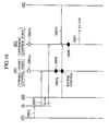
- FIG. 16 is a sequence diagram illustrating a control point
changing operation in uplink radio data communications in the
radio data communications system according to the embodiment
of the present invention; and
- FIG. 17 is a sequence diagram illustrating a control point
changing operation in uplink radio data communications in the
radio data communications system according to the embodiment
of the present invention.
-
DETAILED DESCRIPTION OF THE INVENTION
<The Configuration of Radio Data Communications System in a
First Embodiment of the Invention>
-
The configuration of a radio data communications system
according to a first embodiment of the present invention will
be described with reference to FIGS. 4 to 7. This embodiment
will be described with an exemplary radio data communications
system adopting a router network as described above.
-
In the radio data communications system according to this
embodiment, when a mobile terminal MN 1 performs soft handover
in downlink radio data communications in which a first radio
network controller (e.g., a router RT 2) transmits data to the
mobile terminal MN 1 via second radio network controllers (e.g.,
access routers AR 1 and AR 2) and base stations (e.g., access
points AP 1 to AP 3), or in uplink radio data communications
in which the mobile terminal MN 1 transmits data to the first
radio network controller (e.g., the router RT 2) via base
stations (e.g., the access points AP 1 to AP 3) and the second
radio network controllers (e.g., the access router AR 1 and AR
2), at least one of the first radio network controller (e.g.,
the router RT 2) and the second radio network controller (e.g.,
the access router AR 1) performs a soft handover process for
allowing soft handover of the mobile terminal MN 1.
-
The soft handover process for the mobile terminal MN 1
in downlink radio data communications includes the steps of
determining a first transmission timing of transmitting data
to all base stations (e.g. , the access points AP 1 to AP 3) to
which the mobile terminal MN 1 is connected when performing the
soft handover, dividing the data and providing a sequence number
to each data fragment, and transmitting the data fragments to
all the base stations (e.g., the access points AP 1 to AP 3)
at the first transmission timing.
-
The soft handover process for the mobile terminal MN 1
in uplink radio data communications includes the steps of
performing selective combining of data fragments sent from all
base stations (e.g., the access points AP 1 to AP 3) to which
the mobile terminal MN 1 is connected when performing the soft
handover, and reconstructing data from the selectively combined
data fragments.
-
In the radio data communications system according to this
embodiment, when the mobile terminal MN 1 is performing the soft
handover, a radio network controller performing the soft
handover process for the mobile terminal MN 1 is changed.
-
As shown in FIG. 4, the radio data communications system
according to this embodiment has the mobile terminal MN 1, a
corresponding node CN 1 of the mobile terminal MN 1, a plurality
of routers RT 1 to RT 3, a plurality of access routers AR 1 to
AR 4, a plurality of access points AP 1 to AP 8, and a control
server 50.
-
In this embodiment, a network of a tree structure is
adopted as a router network. The present invention is not
limited thereto and a network of a desired form may be adopted
instead.
-
As shown in FIG. 5, The mobile terminal MN 1 includes a
transmitting unit 11, a receiving unit 12, a radio environment
monitoring unit 13, and a synchronization controlling unit 14.
Here, the maximum number of access point APs to which the mobile
terminal MN 1 can be connected simultaneously is three, and only
one event such as the addition or removal of a branch occurs
at a time.
-
The transmitting unit 11 transmits data in L2 frame format
to an access point AP, and notifies the control server 50 of
the radio environment between the mobile terminal MN 1 and an
access point AP. The receiving unit 12 receives data in L2 frame
format, the reception timing of the data, and so on, from an
access point AP.
-
The radio environment monitoring unit 13 monitors the
radio environment between the mobile terminal MN 1 and an access
point AP. When detecting that the radio environment between
the mobile terminal MN 1 and a given access point AP becomes
better or worse, the radio environment monitoring unit 13
notifies the control server 50 of that fact via the transmitting
unit 11. The radio environment monitoring unit 13 may be
configured to notify the control server 50 of the addition of
a branch to a given access point AP or the removal of the branch
via the transmitting unit 11.
-
The synchronization controlling unit 14 controls
synchronization between the mobile terminal MN 1 and a given
access point AP, an access router AR and/or a router RT based
on the reception timing of the data.
-
The routers RT 1 to RT 3 have the function of exchanges
for performing an exchanging process of data in L3 frame format
(e.g., IP packets). The access routers AR 1 to AR 4 are routers
for accommodating access point APs. For example, the access
points AP 1 to AP 8 are radio base stations.
-
As shown in FIG. 6, a router RT or an access router AR
includes a receiving unit 31, a transmitting unit 32, a
measuring unit 33, a transmission timing determining unit 34,
a synchronization controlling unit 35, a data dividing unit 36,
a sequence number providing unit 37, a duplicating unit 38, a
selectively combining unit 39, a reconstructing unit 40, and
a retransmission controlling unit 41.
-
The receiving unit 31 receives downlink data (in L2 frame
format or L3 frame format), uplink data (in L2 frame format or
L3 frame format), control point change information from the
control server 50, synchronization information such as
transmission timing, timing difference and data delay, a
sequence number, and the like.
-
That is, the receiving unit 31 serves as a notification
receiver configured to receive a notification instructing the
router to perform the soft handover process for the mobile
terminal MN 1 as a first or second radio network controller (an
uppermost control point or a lower control point), or not to
perform the soft handover process for the mobile terminal MN
1.
-
The transmitting unit 32 transmits uplink data (in L2
frame format or L3 frame format), downlink data (in L2 frame
format or L3 frame format), synchronization information such
as transmission timing, timing difference and data delay, a
sequence number and the like.
-
The measuring unit 33 measures data delay and timing
difference between the router and an upper router RT, a lower
router RT (access router AR) or an access point AP, when the
router serves as a control point.
-
When control point change information (notification)
instructing the first radio network controller (e.g., the
router RT 2) to operate as an uppermost control point is received,
the transmission timing determining unit 34 provided in the
first radio network controller (e.g., the router RT 2)
determines a first transmission timing of transmitting data to
a base station (e.g., the access point AP 3) managed by the first
radio network controller (e.g., the router RT 2) among base
stations (e.g., the access points AP 1 to AP 3) to which the
mobile terminal MN 1 is connected when performing soft handover,
and a second transmission timing of transmitting data to the
second radio network controller (e.g., the access router AR 1)
operating as a lower control point.
-
When control point change information (notification)
instructing the second radio network controller (e.g., the
access router AR 1) to operate as a lower control point is
received, the transmission timing determining unit 34 provided
in the second radio network controller (e.g. , the access router
AR 1) determines a first transmission timing of transmitting
data to base stations (e.g., the access points AP 1 and AP 2)
managed by the second radio network controller (e.g., the access
router AR 1) among base stations (e.g., the access points AP
1 to AP 3) to which the mobile terminal MN 1 is connected when
performing soft handover.
-
When the radio network controller operates as a control
point, the synchronization controlling unit 35 controls
synchronization between the radio network controller and an
upper or lower router RT (access router AR) and the mobile
terminal MN 1, based on synchronization information such as
transmission timing, data delay and timing difference.
-
In this embodiment, when control point change information
(notification) instructing the first radio network controller
(e.g., the router RT 2) to operate as an uppermost control point
is received, the transmitting unit 32 and the synchronization
controlling unit 35 provided in the first radio network
controller (e.g., the router RT 2) constitute a data transmitter
configured to transmit at the second transmission timing data
fragments to the second radio network controller (e.g., the
access router AR 1) operating as a lower control point, and also
to transmit at the first transmission timing data fragments to
a base station (e.g. , the access point AP 3) managed by the first
radio network controller (e.g., the router RT 2) among base
stations (e.g., the access points AP 1 to AP 3) to which the
mobile terminal MN 1 is connected when performing soft handover.
-
In this embodiment, when control point change information
(notification) instructing the first radio network controller
(e.g., the router RT 2) to operate as an uppermost control point
is received and there is no lower control point, the
transmitting unit 32 and the synchronization controlling unit
35 provided in the first radio network controller (e.g., the
router RT 2) constitute a data transmitter configured to
transmit at the first transmission timing data fragments to all
base stations (e.g., the access points AP 1 to AP 3) to which
the mobile terminal MN 1 is connected when performing soft
handover.
-
When control point change information (notification)
instructing the second radio network controller (e.g., the
access router AR 1) to operate as a lower control point is
received, the transmitting unit 32 and the synchronization
controlling unit 35 provided in the second radio network
controller (e.g., the access router AR 1) constitute a data
transmitter configured to transfer at the first transmission
timing data fragments transmitted from the first radio network
controller (e.g., the router RT 2) to base stations (e.g., the
access points AP 1 and AP 2) managed by the second radio network
controller (e.g., the access router AR 1) among base stations
(e.g., the access points AP 1 to AP 3) to which the mobile
terminal MN 1 is connected when performing soft handover.
-
When control point change information (notification)
instructing the router not to operate as a control point is
received, the transmitting unit 32 and the synchronization
controlling unit 35 transfer data downward without caring the
transmission timing.
-
When control point change information (notification)
instructing the first radio network controller (e.g., the
router RT 2) to operate as an uppermost control point is received,
the data dividing unit 36 provided in the first radio network
controller (e.g., the router RT 2) divides downlink data in L3
frame format into data fragments in L2 frame format. When
control point change information (notification) instructing
the router not to operate as a control point is received, the
data dividing unit 36 stops the data dividing process.
-
When control point change information (notification)
instructing the router to operate as an uppermost control point
(the first radio network controller) is received, the sequence
number providing unit 37 provides a sequence number to each data
fragment (in L2 frame format) based on the sequence number
providing status. When control point change information
(notification) instructing the router not to operate as a
control point is received, the sequence number providing unit
37 stops the sequence number providing process.
-
When control point change information (notification)
instructing the first radio network controller (e.g., the
router RT 2) to operate as an uppermost control point is received,
the sequence number providing unit 37 provided in the first
radio network controller (e.g., the router RT 2) adds
information requesting the sequence number providing status (a
sequence number providing status notification request bit) to
a data fragment for transmission to the second radio network
controller (e.g., the access router AR 1), cooperating with the
transmitting unit 32.
-
The sequence number providing unit 37 can take over the
sequence number providing status from the second radio network
controller (e.g., the access router AR 1) according to a
sequence number provided to the data fragment added with the
information requesting the sequence number providing status
(sequence number providing status notification request bit),
given by the second radio network controller (e.g., the access
router AR 1), and the number of data fragments having
transmitted since the data fragment added with the information
requesting the sequence number providing status (sequence
number providing status notification request bit) was
transmitted, until the sequence number is received.
-
The duplicating unit 38 performs a duplication process
for data fragments a number of times equal to the number of base
stations to transmit the data when the router operates as a
control point.
-
When control point change information (notification)
instructing the router (e.g., the router RT 2) to operate as
an uppermost control point is received, the selectively
combining unit 39 performs selective combining of data
fragments received from all base stations (e.g., the access
points AP 1 to AP 3) to which the mobile terminal MN 1 is connected
when performing soft handover.
-
When control point change information (notification)
instructing the router (e.g., the access router AR 1) to operate
as a lower control point is received, the selectively combining
unit 39 performs selective combining of data fragments received
from base stations (e.g., access points AP 1 and AP 2) managed
by the router (e.g., the access router AR 1) among all base
stations (e.g., the access points AP 1 to AP 3) to which the
mobile terminal MN 1 is connected when performing soft handover.
-
When control point change information (notification)
instructing the router not to operate as a control point is
received, the selectively combining unit 39 does not perform
selective combining of data fragments.
-
The reconstructing unit 40 reconstructs data in L3 frame
format from the selectively combined data fragments (in L2 frame
format), when control point change information (notification)
instructing the router to operate as an uppermost control point
is received.
-
The reconstructing unit 40 does not reconstruct the data,
when control point change information (notification)
instructing the router to operate as a lower control point is
received or control point change information (notification)
instructing the router not to operate as a control point is
received.
-
The retransmission controlling unit 41 performs
L2-frame-unit retransmission control between the router and the
mobile terminal MN 1, when control point change information
(notification) instructing the router to operate as an
uppermost control point is received.
-
The control server 50 is located in the network and
connected to devices in the network, performing an auxiliary
function for a control point performing the soft handover
process in the network. As shown in FIG. 7, The control server
50 includes a receiving unit 51, a transmitting unit 52, and
a control point managing unit 53.
-
The receiving unit 51 receives a radio environment
notification from the mobile terminal MN 1. The transmitting
unit 52 provides a notification of control point change
information generated by the control point managing unit 52 to
radio network controllers (e.g., the router RT 2 and the access
router AR 1) related to the change.
-
The control point managing unit 52 generates control
point change information based on the radio environment
notification. That is, the control point managing unit 52
constitutes a determiner configured to determine a change of
radio network controllers for performing the soft handover
process for the mobile terminal MN 1, in response to a
notification from the mobile terminal MN 1, when the mobile
terminal MN 1 is performing soft handover.
<The Operation of the Radio Data Communications System in the
Embodiment>
-
The operation of the radio data communications system
according to this embodiment will be described with reference
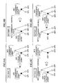
to FIGS. 8A to 17. In the embodiment, description will be made
on four patterns of operation of the radio data communications
system when changing control points as shown in FIGS. 8A to 8D.
-
First, with reference to FIGS. 8A to 13, the operation
of the radio data communications system in downlink radio
communications will be described.
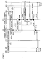
«Pattern 1»
-
As shown in FIG. 8A, in pattern 1, the mobile terminal
MN 1 is already connected to the access points AP 1 and AP 2
in the network shown in FIG. 4, and only the access router AR
1 constitutes a control point. The mobile terminal MN 1 then
adds a branch to the access point AP 3, so that the router RT
2 is added as a control point (switching to a soft handover
process performed by the access router AR 1 and the router RT
2, simultaneously).
-
In short, in pattern 1, a new control point (router RT
2) is placed above an uppermost control point (access router
AR 1) which is uppermost until that time.
-
In that case, the radio data communications system in this
embodiment can operate as shown in FIG. 9, thereby performing
a control point change without causing loss of data.
-
As shown in FIG. 9, in step 101, a branch to the access
point AP 3 has not been added, only the access router AR 1
constitutes a control point, and synchronization is established
between the access points AP 1 and AP 2 and the mobile terminal
MN 1.
-
In step 102, the mobile terminal MN 1 detects that the
radio environment between the mobile terminal MN 1 and the
access point AP 3 becomes better, and notifies the control
server 50 of the fact.
-
Upon the notification, the control server 50 determines
the addition of a branch to the access point AP 3 and, as a result
of computation, determines the addition of the router RT 2, for
example, as a control point.
-
In step 103a, the control server 50 transmits to the access
router AR 1 control point change information instructing that
the upper router RT 2 becomes a control point. In step 103b,
the control server 50 transmits to the router RT 2 control point
change information instructing it to become an uppermost
control point. In step 103c, the control server 50 transmits
to the access point AP 3 control point change information
instructing that the router RT 2 becomes its directly upper
control point.
-
In step 104, the router RT 2 (a new uppermost control
point), upon receiving the control point change information,
performs a process of taking over a sequence number (SN) added
to a data fragment from the access router AR 1 (a former uppermost
control point). The details will be described below.
-
In step 105, at the completion of the process of taking
over a sequence number in step 104, the router RT 2 transmits
to the access router AR 1 data fragments in L2 frame format
resulting from the division of data in L3 frame format, added
with sequence numbers. At that time, the access router AR 1
stops the sequence number providing process and transmits the
data fragments received from the router RT 2 as they are at the
existing transmitting timing to the access points AP 1 and AP
2.
-
In step 106, the access router AR 1 notifies the router
RT 2 of synchronization information having been used until that
time such as data delays and timing differences (clock timing
differences) between the access points AP 1 and AP 2 and the
mobile terminal MN 1 and transmission timings.
-
In step 107, the router RT 2 measures a data delay and
a timing difference (clock timing difference) between the
router RT 2 and the access router AR 1.
-
In step 108, the router RT 2 determines the timing of
transmission from the router RT 2 to the access router AR 1 based
on the measurement in step 107. At that time, the timing of
transmission below the access router AR 1, that is, the timing
of transmission from the access router AR 1 to the access points
AP 1 and AP 2 is not changed.
-
In step 109, the mobile terminal MN 1 measures a difference
between a clock timing given by the access point AP 1 or AP 2
and a clock timing given by the access point AP 3, and notifies
the router RT 2 of the timing difference.
-
In step 110, the router RT 2 measures a data delay and
a timing difference between the router RT 2 and the access point
AP 3, and determines the timing of transmission from the access
point AP 3 to the mobile terminal MN 1 and the timing of
transmission from the router RT 2 to the access point AP 3. Then,
the router RT 2 notifies the access point AP 3 of the timing
of transmission from the access point AP 3 to the mobile terminal
MN 1.
-
In step 111, at the completion of operation up to step
110, the router RT 2 starts a duplication process of data and
a data transmission process (timing transmission process) to
the access router AR 1 and the access point AP 3 according to
the determined transmission timings, in addition to the data
dividing process and the sequence number providing process
having been performed up to that time.
-
The timing transmission process to the access router AR
1 may have been started at the completion of step 108. Also,
the transmission process of data fragments may be done by
encapsulation in L3 frame (e.g., IP encapsulation) when
necessary.
-
After step 111, when receiving data in L3 frame format
from the corresponding node CN 1 via the router RT 1, the router
RT 2 performs on the data the process of dividing into data in
L2 frame format, the sequence number providing process and the
duplicating process, in step 112a.
-
In step 112b, the router RT 2 performs the process of
timing transmission to the access router AR 1, and in step 12c,
the router RT 2 performs the process of timing transmission to
the access point AP 3.
-
In step 113a, the access router AR 1, upon receiving the
data (in L2 frame format) from the router RT 2, performs the
duplicating process, and in step 113b, the access router AR 1
performs the timing transmission process to the access points
AP 1 and AP 2.
-
In step 114, the access points AP 1 to AP 3 perform the
process of timing transmission to the mobile terminal MN 1 at
the specified transmission timings.
-
Steps 106 to 108 may be performed in parallel with steps
109 and 110.
-
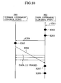
Now the sequence number taking over process (step 104)
will be described with reference to FIG. 10.
-
If a sequence number provided at the access router AR 1
as the former uppermost control point is not sequentially
followed by a sequence number first provided at the router RT
2 as the new uppermost control point in the sequence number
taking over process, the control point change can cause lack
of continuity of sequence numbers, largely increasing a data
transmission interval, or in the worst case, cause loss of data.
-
Control as shown in FIG. 10 can avoid the above problems,
that is, can allow sequence number taking over with maintained
continuity.
-
As shown in FIG. 10, in step 201, the router RT 2 receives
data in L3 frame format from above (e.g., the router RT 1). In
step 202, the router RT 2 starts the process of dividing the
received data in L3 frame format into data fragments in L2 frame
format. The router RT 2, however, does not start the sequence
number providing process.
-
In step 203, the router RT 2 adds to a data fragment
information requesting the sequence number providing status.
For example, the router RT 2 turns on a sequence number providing
status notification request bit provided at the head of a data
fragment.
-
In step 204, the router RT 2 transmits the data fragment
to the access router AR 1. Thereafter, before step 207, the
router RT 2 performs the data dividing process, and continues
the process of data transmission to the access router AR 1,
counting the number of data fragments transmitted during that
period.
-
In step 205, the access router AR 1 stops the data dividing
process while continuing the provision of sequence numbers
following a number provided last to the data fragments (in L2
frame format) received from the router RT 2 for downward
transmission (i.e., to the access points AP 1 and AP 2).
-
The access router AR 1, when recognizing in step 205 that
the sequence number providing status notification request bit
is set in the data fragment received from the router RT 2, in
step 206, notifies the router RT 2 of a sequence number provided
to the first data fragment with the sequence number providing
status notification request bit set.
-
In step 207, the router RT 2 calculates the number of data
fragments in L2 frame format transmitted to the access router
AR 1 after step 202, and a sequence number to be provided to
the next data fragment in L2 frame format to be transmitted to
the access router AR 1, based on the sequence number received
in step 206.
-
In step 208, the router RT 2 starts the process of
providing sequence numbers to the following data fragments
based on the calculation in step 207.
«Pattern 2»
-
As shown in FIG. 8B, in pattern 2, the mobile terminal
MN 1 is connected to the access points AP 1 to AP 3 in the network
shown in FIG. 4, and the router RT 2 and the access router AR
1 constitute control points. The mobile terminal MN 1 then
removes the branch to the access point AP 3, so that the router
RT 2 as the control point is removed (switching to a soft handover
process performed only by the access router AR 1).
-
In short, in pattern 2, a control point (access router
AR 1) located as a lower control point is changed to an uppermost
control point.
-
In that case, the radio data communications system
according to this embodiment can operate as shown in FIG. 11,
thereby performing a control point change without causing loss
of data.
-
As shown in FIG. 11, in step 301, before the removal of
the branch to the access point AP 3, synchronization is
established among the router RT 2, the access router AR 1 as
control points, the access points AP 1 to AP 3 and the mobile
terminal MN 1.
-
In step 302, the access point AP 3 notifies the control
server 50 of the removal of the branch from the mobile terminal
MN 1 to the access point AP 3, that is, the disconnection between
the mobile terminal MN 1 and the access point AP 3. Such
notification may be done from the mobile terminal MN 1 to the
control server 50 or may be done from the access point AP 3
detecting the disconnection to the control server 50.
-
Upon the notification, the control server 50 determines
the removal of the router RT 2 from the control points, for
example, as a result of computation.
-
In step 303, the control server 50 transmits to the access
router AR 1 control point change information to instruct that
the upper router RT 2 is removed from the control points and
the access router AR 1 becomes an uppermost control point, and
transmits to the router RT 2 control point change information
to instruct its removal from the control points.
-
In step 304, upon receiving the control point change
information, the router RT 2 (the former uppermost control
point) stops the duplicating process and the data transmitting
process to the access point AP 3.
-
In step 305, the router RT 2 releases the hold of
information on synchronization with the access point AP 3. In
step 306, the router RT 2, which stops serving as a control point,
stops the data dividing process and the sequence number
providing process which have been done until that time.
-
In step 307, the router RT 2 stops the timing transmission
process to the access router AR 1 (the new uppermost control
point), in other words, only relays (transfers) downlink data
to the access router AR 1. The router RT 2 releases the hold
of information on synchronization with the access router AR 1
when necessary.
-
In step 308, the router RT 2 receives data (in L3 frame
format) from the corresponding node CN 1, and in step 310, the
router RT 2 transfers the data to the access router AR 1 without
performing the data dividing process , sequence number providing
process, timing transmission process and the like
-
In step 309, in order to avoid the event that data not
requiring processing gets ahead of data being processed,
reversing the initial order of data during transmission to the
access router AR 1, the router RT 2 may perform buffer control
such as a queuing process of buffering data not requiring
processing until the completion of transmission of data being
processed.
-
In step 311, the access router AR 1 detects that data first
received is not subjected to the data dividing process and the
sequence number providing process, In step 312, the access
router AR 1 performs on the data and data received after the
data the data dividing process, providing sequence numbers
following a sequence number provided last. As a result, the
continuity of sequence numbers can be maintained.
-
In step 313, the access router AR 1 continuously performs
the timing transmission process to the access points AP 1 and
AP 2 at the transmission timing used until that time. In step
314, the access points AP 1 and AP 2 continue the timing
transmission process at transmission timings used until that
time to the mobile terminal MN 1.
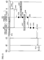
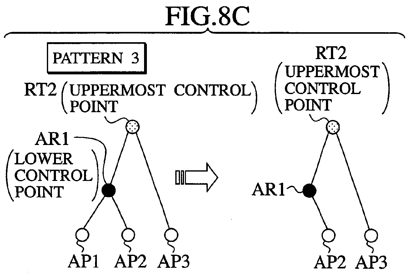
«Pattern 3»
-
As shown in FIG. 8C, in pattern 3, the mobile terminal
MN 1 is connected to the access points AP 1 to AP 3 in the network
shown in FIG. 4, and the router RT 2 and the access router AR
1 constitute control points. The mobile terminal MN 1 then
removes a branch to the access point AP 1, so that the access
router AR 1 is removed from the control points (that is,
switching to a soft handover process performed only by the
router RT 2).
-
In short, in pattern 3, a lower control point (access
router AR 1) other than an uppermost control point (router RT
2) is removed from the control points.
-
In that case, the radio data communications system
according to this embodiment can operate as shown in FIG. 12,
performing a control point change without causing loss of data.
-
As shown in FIG. 12, in step 401, before the removal of
the branch to the access point AP 1, synchronization is
established among the router RT 2, the access router AR 1 as
the control points, the access points AP 1 to AP 3 and the mobile
terminal MN 1.
-
In step 402, the access point AP 1 notifies the control
server 50 of the removal of the branch from the mobile terminal
MN 1 to the access point AP 1, in other words, the disconnection
between the mobile terminal MN 1 and the access point AP 1. Such
notification may be done from the mobile terminal MN 1 to the
control server 50, or may be done from the access point AP 1
detecting the disconnection to the control server 50.
-
In step 403, upon the notification, the control server
50 determines the removal of the access router AR 1 from the
control points, for example, as a result of computation.
-
The control server 50 transmits to the access router AR
1 control point change information to instruct its removal from
the control points, transmits to the access point AP 2 control
point change information to instruct that its directly upper
control point is changed to the router RT 2, and transmits to
the router RT 2 control point change information to instruct
that the lower access router AR 1 is removed from the control
points and the access point AP 2 is directly below.
-
In step 404, upon receiving the control point change
information, the access router AR 1 (the former lower control
point) stops the duplicating process and the data transmitting
process to the access point AP 1.
-
In step 405, the access router AR 1 releases the hold of
information on synchronization with the access point AP 1 when
necessary. The access router AR 1, however, continuously
performs the timing transmission process to the access point
AP 2.
-
In step 406, upon receiving the control point change
information transmitted in step 403, the router RT 2
continuously serving as the uppermost control point measures
a data delay and a timing difference between the router RT 2
and the access point AP 2.
-
In step 407, the access router AR 1 transmits to the router
RT 2 synchronization information such as data delay, timing
difference and transmission timing used until that time. The
router RT 2, if having received such synchronization
information, may skip step 407.
-
In step 408, the router RT 2 determines the timing of
transmission to the access point AP 2 based on the measurement
in step 406 and the synchronization information in step 407.
The timing of transmission from the access point AP 2 to the
mobile terminal MN 1 is not changed.
-
In step 409, the router RT 2 notifies the access router
AR 1 of its stopping the timing transmission process to the
access router AR 1, and in step 410, releases the hold of
information on synchronization with the access router AR 1 when
necessary.
-
In step 411, upon the notification, the access router AR
1 stops the process of timing transmission of data received from
the router RT 2 to the access point AP 2, and only relays
(transfers) the data to the access point AP 2.
-
In step 412, the router RT 2 receives data in L3 frame
format from above (e.g., the router RT 1), and in step 413, the
router RT 2 subjects the received data to the data dividing
process, sequence number providing process and duplicating
process to the access points AP 2 and AP 3 as done until that
time.
-
In step 414a, the router RT 2 performs the process of
timing transmission of the data (in L2 frame format) to the
access points AP 2, and in step 414b, the router RT 2 performs
the process of timing transmission of the data (in L2 frame
format) to the access points AP 3.
-
The access router AR 1 may be configured to perform buffer
control on data received from the router RT 2 and then transfer
the data to the access point AP 2.
-
In step 415, the access points AP 2 and AP 3 perform the
process of timing transmission to the mobile terminal MN 1 at
transmission timings used until that time.
«Pattern 4»
-
As shown in FIG. 8D, in pattern 4, the mobile terminal
MN 1 is connected to the access points AP 2 and AP 3 in the network
shown in FIG. 4, and only the router RT 2 constitutes a control
point. The mobile terminal MN 1 then adds a branch to the access
point AP 1, so that the access router AR 1 is added as a control
point (switching to a soft handover process performed by the
router RT 2 and the access router AR 1).
-
In short, in pattern 4, a new control point (the access
router AR 1) is added in a location lower than an uppermost
control point (the router RT 2).
-
In that case, the radio data communications system
according to this embodiment can operate as shown in FIG. 13,
thereby performing a control point change without causing loss
of data.
-
As shown in FIG. 13, in step 501, before the addition of
a branch to the access point AP 1, synchronization is
established among the router RT 2 as the control point, the
access points AP 2 and AP 3 and the mobile terminal MN 1.
-
In step 502, the mobile terminal MN 1 notifies the control
server 50 of the fact that a radio environment between the mobile
terminal MN 1 and the access point AP 1 becomes better.
-
In step 503, upon the notification, the control server
50 determines the addition of a branch to the access point AP
1, and, as a result of computation, determines the addition of
the access router AR 1 as a control point, for example.
-
Then, the control server 50 transmits to the access point
AP 2 control point change information to instruct that the
access router AR 1 becomes its directly upper control point,
transmits to the access router AR 1 control point change
information to instruct it to become a control point between
the access points AP 1 and AP 2 and the router RT 2, and transmits
to the router RT 2 control point change information to instruct
that the access point AP 2 ceases to be its directly lower access
point AP and the access router AR 1 is added as a new lower control
point.
-
Upon receiving the control point change information, the
access router AR 1 measures a data delay and a timing difference
between the access router AR 1 and the directly lower access
points AP 2 in step 504a, and measures a data delay and a timing
difference between the access router AR 1 and the directly lower
access points AP 1 in step 504b.
-
In step 505, the access router AR 1 notifies the router
RT 2 of synchronization information including the data delays
and timing differences measured in step 504.
-
In step 506, the mobile terminal MN 1 notifies the router
RT 2 of a measured timing difference between a clock given by
the access point AP 2 (or the access point AP 3) and a clock
given by the access point AP 1.
-
In step 507, the router RT 2 measures a data delay and
a timing difference between the router RT 2 and the access router
AR 1.
-
In step 508, the router RT 2 determines the timing of
transmission from the access router AR 1 to the access points
AP 1 and AP 2, the timing of transmission from the router RT
2 to the access router AR 1, and the timing of transmission from
the access point AP 1 to the mobile terminal MN 1, based on
synchronization information used until that time,
synchronization information given in step 505, synchronization
information (timing difference) given in step 506, and
synchronization information measured in step 507.
-
In step 509, the router RT 2 notifies the access router
AR 1 of the timing of transmission from the access router AR
1 to the access points AP 1 and AP 2, and in step 510, the router
RT 2 notifies the access point AP 1 of the timing of transmission
from the access point AP 1 to the mobile terminal MN 1.
-
In step 511, the router RT 2 stops the direct transmission
of the following data to the access point AP 1. Specifically,
the router RT 2 transmits the following data to the access router
AR 1, and the access router AR 1 performs the timing transmission
process on the data. The router RT 2 releases the hold of the
information on synchronization with the access point AP 1 when
necessary.
-
In step 512, the router RT 2 receives data in L3 frame
format from the corresponding node CN 1 via the router RT 1.
-
In step 513, the router RT 2 subjects the received data
to the data dividing process, sequence number providing process
using sequence numbers following a number used last, and the
duplicating process for the access router AR 1 and the access
point AP 3.
-
In step 514a, the router RT 2 performs on the data (in
L2 frame format) the timing transmission process to the access
router AR 1, and in step 514b, the router RT 2 performs on the
data (in L2 frame format) the timing transmission process to
the access point AP 3.
-
In step 515, the access router AR 1 subjects the data (in
L2 frame format) to the duplicating process for the access
points AP 1 and AP 2. Then, in step 516, the access router AR
1 performs on the data (in L2 frame format) the timing
transmission process to the access points AP 1 and AP 2.
-
In step 517, the access points AP 2 and AP 3 continuously
perform the timing transmission process to the mobile terminal
MN 1, and the access point AP 1 performs the timing transmission
process based on the given new transmission timing.
-
Second, with reference to FIGS. 14 to 17, the operation
of the radio data communications system in uplink radio
communications will be described. Patterns 1 to 4 described
below are identical to those in the above-described downlink
radio communications.
«Pattern 1»
-
AS shown FIG. 14, in step 601, before the addition of a
branch to the access point AP 3, only the access router AR 1
constitutes a control point, and the access router AR 1 performs
on uplink data (in L2 frame format) from the access points AP
1 and AP 2 the selective combining process, the process of
controlling retransmission of the mobile terminal MN 1 (when
necessary, the same is true hereinafter), and the process of
reconstruction into data in L3 frame format.
-
In step 602, the mobile terminal MN 1 notifies the control
server 50 of the fact that the radio environment between the
mobile terminal MN 1 and the access point AP 3 becomes better.
-
Upon the notification, the control server 50 determines
the addition of a branch to the access point AP 3 and, as a result
of computation, determines the addition of the router RT 2, for
example, as a control point.
-
Then, the control server 50 transmits to the access router
AR 1 control point change information to instruct that the upper
router RT 2 becomes a control point in step 603a, transmits to
the router RT 2 control point change information to instruct
it to become an uppermost control point in step 603b, and
transmits to the access point AP 3 control point change
information to instruct that the router RT 2 becomes its
directly upper control point in step 603c.
-
In step 604, the router RT 2 (a new uppermost control
point), upon receiving the control point change information,
starts the selective combining process, retransmission
controlling process, and reconstruction controlling process.
-
In step 605a, the router RT 2 notifies the access router
AR 1 (the former uppermost control point) of the start of
reception of uplink data (in L2 frame format) , and in step 605b,
the router RT 2 notifies the access point AP 3 of the start of
reception of uplink data (in L2 frame format).
-
In step 606, the access router AR 1 receiving the
notification of the reception start then only continues the
selective combining process and stops the retransmission
controlling process and the reconstructing process on data in
L2 frame format received from the access points AP 1 and AP 2.
-
In step 607, the access router AR 1 receives data (data
fragments) in L2 frame format from the access points AP 1 and
AP 2, and in step 608, the access router AR 1 performs the
selective combining process on data having the same sequence
numbers.
-
In step 609, the access router AR 1 transmits the
selectively combined data in L2 frame format to the router RT
2. At that time, the access router AR 1 performs IP
encapsulation or the like on the data when necessary.
-
In step 610, the router RT 2 receives uplink data (in L2
frame format) from the access point AP 3.
-
In step 611, the router RT 2 performs the selective
combining process on data having the same sequence numbers of
data sent from the access router AR 1 and data sent from the
access point AP 3, and performs the retransmission controlling
process and the reconstructing process on the selectively
combined data.
-
In step 612, the router RT 2 transmits the reconstructed
data in L3 frame format to the destination corresponding node
CN 1 via the router RT 1.
-
During steps 604 to 609, in order to prevent double
generation of data and loss of data, the following measures can
be taken.
-
The router RT 2 (the new uppermost control point) forwards
reconstructed data received from the access router AR 1 (the
former uppermost control point) as it is to the corresponding
node CN 1.
-
The router RT 2 (the new uppermost control point) starts
the selective combining process, retransmission controlling
process and reconstructing process on first data in L2 frame
format received from the access router AR 1 (the former
uppermost control point), and discards data in L2 frame format
received from the access point AP 3 but not received from the
access router AR 1.
-
Such data in L2 frame format has already been
reconstructed at the access router AR 1. If the data from the
access point AP 3 was also subjected to the reconstructing
process, the same L3 frame format data would be double
generated.
-
There is a possibility in that the access router AR 1 (the
former uppermost control point), when reconstructing data in
L3 frame format in step 606, will transmit the next data in L2
frame format upward (to the router RT 2) before completing the
L3 frame format data. To ensure the reconstruction of data in
L3 frame format, the following controls are possible, for
example.
-
In a first example, the access router AR 1 (the former
uppermost control point) completes the reconstruction of L3
frame format data being reconstructed, and starts transmitting
the next data in L2 frame format to the router RT 2 (the new
uppermost control point) without performing the reconstructing
process thereon.
-
In a second example, the access router AR 1 (the former
uppermost control point) and the router RT 2 (the new uppermost
control point) reconstruct respective halves of data in L3 frame
format which are then combined together at one of them (e.g.,
the router RT 2).
«Pattern 2»
-
As shown in FIG. 15, in step 701a, the access router AR
1 (a lower control point) performs only the selective combining
process on L2 frame format data sent from the access points AP
1 and AP 2, and transmits the selectively combined L2 frame
format data to the router RT 2 as an upper control point.
-
In step 701b, the router RT 2 (an uppermost control point)
performs the selective combining process, retransmission
controlling process and reconstructing process on the L2 frame
format data sent from the access router AR 1 and the access point
AP 3, and transmits the reconstructed L3 frame format data to
the corresponding node CN 1.
-
In step 702, the access point AP 3 notifies the control
server 50 of the removal of a branch from the mobile station
MN 1 to the access point AP 3. Such notification may be done
from the mobile terminal MN 1 to the control server 50 or may
be done from the access point AP 3 detecting the disconnection
to the control server 50.
-
Upon the notification, the control server 50 determines
the removal of the router RT 2 from the control points, for
example, as a result of computation.
-
In step 703, the control server 50 transmits to the access
router AR 1 control point change information to instruct that
the upper router RT 2 is removed from the control points and
the access router AR 1 becomes an uppermost control point, and
transmits to the router RT 2 control point change information
to instruct its removal from the control points.
-
In step 704, upon receiving the control point change
information, the access router AR 1 (the new uppermost control
point) starts the retransmission controlling process and
reconstructing process as well as the selective combining
process on L2 frame format data from the access points AP 1 and
AP 2. In step 705, the router RT 2 (the former uppermost control
point) is notified of the fact.
-
In step 706, the router RT 2 receiving the notification
in step 705 stops the selective combining process,
retransmission controlling process and reconstructing process,
and releases resources for the control. If still receiving L2
frame format data from the access router AR 1, however, the
router RT 2 stops these processes after the completion of the
processes on the data.
-
In step 707, the access router AR 1 receives L2 frame
format data from the access points AP 1 and AP 2, and in step
708, the access router AR 1 performs the selective combining
process, retransmission controlling process and
reconstructing process on the received data.
-
In step 709, the access router AR 1 transmits the
reconstructed L3 frame format data to the corresponding node
CN 1 via the router RT 2. Here the router RT 2 may be configured
to perform buffer control on data from the access router AR 1.
-
During steps 703 to 709, the router RT 2 (the former
uppermost control point), when reconstructing L3 frame format
data in step 703, cannot receive the following L2 frame format
data, so that there is a possibility in that the L3 frame format
data cannot be completed.
-
In such a case, the access router AR 1 (the new uppermost
control point) may reconstruct the L3 frame format data from
the middle of the data. To ensure the reconstruction of L3 frame
format data, the following controls, for example, are
effective.
-
In a first example, in step 703, the access router AR 1
(the new uppermost control point) determines whether L2 frame
format data to transmit is data in the middle of L3 frame format
data, and if so, transmits the middle data to the router RT 2
(the former uppermost control point), and starts the
reconstructing process using data constituting first part of
the following L3 frame format data.
-
In a second example, the router RT 2 (the former uppermost
control point) and the access router AR 1 (the new uppermost
control point) reconstruct respective halves of L3 frame format
data which are then combined together at one of them (e.g., the
router RT 2).
«Pattern 3»
-
As shown in FIG. 16, in step 801a, before the removal of
a branch to the access point AP 1, the access router AR 1 as
a lower control point performs only the selective combining
process on L2 frame format data from the access points AP 1 and
AP 2, and transmits the selectively combined L2 frame format
data to the router RT 2 as an upper control point.
-
In step 801b, the router RT 2 (an uppermost control point)
performs the selective combining process, retransmission
controlling process and reconstructing process on L2 frame
format data from the access router AR 1 and the access point
AP 3, and transmits the reconstructed L3 frame format data to
the corresponding node CN 1.
-
In step 802, the access point AP 1 notifies the control
server 50 of the removal of the branch from the mobile station
MN 1 to the access point AP 1. Such notification may be done
from the mobile terminal MN 1 to the control server 50, or may
be done from the access point AP 1 detecting the disconnection
to the control server 50.
-
Upon the notification, the control server 50 determines
the removal of the access router AR 1 from the control points,
for example, as a result of computation.
-
In step 803, the control server 50 transmits to the access
router AR 1 control point change information to instruct its
removal from the control points, transmits to the access points
AP 2 control point change information to instruct that its
directly upper control point is changed to the router RT 2, and
transmits to the router RT 2 control point change information
to instruct that the lower access router AR 1 is removed from
the control points and the access point AP 2 is directly below.
-
In step 804, upon receiving the control point change
information, the access router AR 1 (the former lower control
point) stops the selective combining process on L2 frame format
data sent from the access points AP 1 and AP 2. Then, the access
router AR 1 relays (transfers) the data to the router RT 2.
-
In step 805a, the router RT 2 receives the L2 frame format
data from the access point AP 2 via the access router AR 1, and
in step 805b, the router RT 2 also receives L2 frame format data
from the access point AP 3. Here the access router AR 1 may
perform buffer control on the L2 frame format data from the
access point AP 2.
-
In step 806, the router RT 2 continuously performs the
selective combining process, retransmission controlling
process and reconstructing process on the L2 frame format data
received from the access points AP 2 and AP 3.
-
In step 807, the router RT 2 transmits the completed L3
frame format data to the corresponding node CN 1 via the router
RT 1.
«Pattern 4»
-
As shown in FIG. 17, in step 901, before the addition of
a branch to the access point AP 1, the router RT 2 as an uppermost
control point performs the selective combining process,
retransmission controlling process and reconstructing process
on L2 frame format data. The access router AR 1 only relays
(transfers) L2 frame format data from the access point AP 2 to
the router RT 2.
-
In step 902, the mobile terminal MN 1 notifies the control
server 50 of the fact that the radio environment between the
mobile terminal MN 1 and the access point AP 1 becomes better.
-
Upon the notification, the control server 50 determines
the addition of the branch to the access point AP 1, and, as
a result of computation, determines the addition of the access
router AR 1 as a control point, for example.
-
In step 903, the control server 50 transmits to the access
point AP 2 control point change Information to instruct that
the access router AR 1 becomes its directly upper control point,
transmits to the access router AR 1 control point change
information to instruct it to become a control point between
the access points AP 1 and AP 2 and the router RT 2, and transmits
to the router RT 2 control point change information to instruct
that the access point AP 2 is not connected directly below and
the access router AR 1 is added as a new lower control point.
-
In step 904, upon receiving the control point change
information, the access router AR 1 starts the selective
combining process on L2 frame format data from the access points
AP 1 and AP 2.
-
In step 905, the access router AR 1 notifies the access
points AP 1 and AP 2 of the start of reception of L2 frame format
data.
-
In step 906, the access router AR 1 receives L2 frame
format data from the access points AP 1 and AP 2. In step 907,
the access router AR 1 performs only the selective combining
process on the received data. In step 908, the access router
AR 1 transmits the selectively combined L2 frame format data
to the router RT 2 as an upper control point.
-
In step 909, the router RT 2 continuously receives L2 frame
format data also from the access point AP 3.
-
In step 910, the router RT 2 continuously performs the
selective combining process, retransmission controlling
process and reconstructing process on the L2 frame format data
from the access router AR 1 and the access point AP 3.
-
In step 911, the router RT 2 transmits the completed L3
frame format data to the corresponding node CN 1 via the router
RT 1.
-
In this embodiment, the maximum number of branches to
which the mobile terminal MN 1 can be connected at a time is
three, so that the number of control points is maximum two. The
present invention, however, is not limited thereto and is
applicable to a desired number of branches and a desired number
of control points.
-
Specifically, in the present invention, it is only
required to determine whether it is an uppermost control point
that is added or removed or the like, and selectively perform
the operation of corresponding one of the above-described four
patterns.
-
The present invention can accommodate every control point
change pattern by an appropriate combination of the
above-described four patterns. For example, when a control
point is added or removed in a transition between a one-branch
state and a two-branch state, the above combination can
accommodate it.
-
If there is a plurality of control points, a router not
serving as a control point may be located in a path therebetween.
In that case, the router only relays data.
<The Function/Effect of the Radio Data Communications System
in the Embodiment>
-
In the radio data communications system according to the
embodiment, a radio network controller (control point)
performing the soft handover process for the mobile terminal
MN 1 can be changed when the mobile terminal MN 1 is performing
soft handover in uplink or downlink radio data communications,
thereby to allow the optimization of the data transmission and
reception path and an effective use of network resources.
-
Further, in the radio data communications system
according to the embodiment, a control point (first radio
network controller) can be placed upstream of the then control
point (second radio network controller) , or processes performed
at a control point (first radio network controller) placed
uppermost until that time can be stopped, or processes performed
at a control point (second radio network controller) placed
downstream of a control point (first radio network controller)
placed uppermost until that time can be stopped, or a control
point (second radio network controller) can be placed
downstream of a control point (first radio network controller)
placed uppermost until that time, which results in a more
flexible optimization of the data transmission and reception
path.
-
In the radio data communications system according to the
embodiment, control point change can be done without impairing
the continuity of sequence numbers provided to data fragments
(in L2 frame format) to be transmitted to the mobile terminal
MN 1 in downlink radio data communications.
-
As described above, the present invention can provide a
radio data communications method, a server and a radio network
controller which allow a change of control points located in
a network without causing loss of data when the mobile terminal
MN 1 is performing a soft handover.
-
Additional advantages and modifications will readily
occur to those skilled in the art. Therefore, the invention
in its broader aspects is not limited to the specific details
and the representative embodiment shown and described herein.
Accordingly, various modifications may be made without
departing from the spirit or scope of the general inventive
concept as defined by the appended claims and their equivalents.