EP1519108A1 - Verfahren zur Erzeugung von überhitztem Dampf, Dampferzeugungsstufe für ein Kraftwerk und Kraftwerk - Google Patents
Verfahren zur Erzeugung von überhitztem Dampf, Dampferzeugungsstufe für ein Kraftwerk und Kraftwerk Download PDFInfo
- Publication number
- EP1519108A1 EP1519108A1 EP04018433A EP04018433A EP1519108A1 EP 1519108 A1 EP1519108 A1 EP 1519108A1 EP 04018433 A EP04018433 A EP 04018433A EP 04018433 A EP04018433 A EP 04018433A EP 1519108 A1 EP1519108 A1 EP 1519108A1
- Authority
- EP
- European Patent Office
- Prior art keywords
- evaporator
- superheater
- heating
- heated
- steam generating
- Prior art date
- Legal status (The legal status is an assumption and is not a legal conclusion. Google has not performed a legal analysis and makes no representation as to the accuracy of the status listed.)
- Granted
Links
Images

Classifications
-
- F—MECHANICAL ENGINEERING; LIGHTING; HEATING; WEAPONS; BLASTING
- F22—STEAM GENERATION
- F22B—METHODS OF STEAM GENERATION; STEAM BOILERS
- F22B1/00—Methods of steam generation characterised by form of heating method
- F22B1/006—Methods of steam generation characterised by form of heating method using solar heat
-
- Y—GENERAL TAGGING OF NEW TECHNOLOGICAL DEVELOPMENTS; GENERAL TAGGING OF CROSS-SECTIONAL TECHNOLOGIES SPANNING OVER SEVERAL SECTIONS OF THE IPC; TECHNICAL SUBJECTS COVERED BY FORMER USPC CROSS-REFERENCE ART COLLECTIONS [XRACs] AND DIGESTS
- Y02—TECHNOLOGIES OR APPLICATIONS FOR MITIGATION OR ADAPTATION AGAINST CLIMATE CHANGE
- Y02E—REDUCTION OF GREENHOUSE GAS [GHG] EMISSIONS, RELATED TO ENERGY GENERATION, TRANSMISSION OR DISTRIBUTION
- Y02E10/00—Energy generation through renewable energy sources
- Y02E10/40—Solar thermal energy, e.g. solar towers
- Y02E10/46—Conversion of thermal power into mechanical power, e.g. Rankine, Stirling or solar thermal engines
Definitions
- the invention relates to a process for the production of superheated steam, in which overheated steam generated in an evaporator in a superheater becomes.
- Such methods are used in particular in power plants such as steam power plants or gas and steam power plants used to generate superheated steam, which is then fed to a steam turbine.
- the invention further relates to a steam generation stage for a power plant, comprising an evaporator for generating steam and a superheater to overheat the steam.
- the invention relates to a power plant and in particular solar thermal Power plant with a steam turbine.
- the invention is based on the object, the aforementioned method so to improve that results in an improved efficiency.
- This object is according to the invention in the aforementioned method achieved in that the evaporator heated separately from the superheater becomes.
- the solution according to the invention can be used for a variety of systems.
- the evaporator can be heated solar thermal or combustion heat.
- the superheater can be heated solar thermal or about combustion heat.
- Trough collector concepts or tower concepts are used, where for the superheater tower concepts are preferred.
- the evaporator is heated independently of the superheater. This eliminates the pinch point condition.
- the individual can be System components can be optimized separately and can be set accordingly set the temperature levels separately in the different systems, so that overall results in improved efficiency.
- the superheater is by means of a Working medium heated.
- the working medium is in particular circulating air.
- the pinch point condition can work fluid with a lower working temperature, the Superheater be supplied.
- the material requirements for a Reduced working medium management, where a total of a higher Efficiency can reach.
- the evaporator of a working medium guide of Working medium for heating the superheater decoupled.
- the working medium which heats the superheater, so does not act on the evaporator.
- the superheater and the evaporator separate Have heat sources for direct heat transfer to steam / water.
- These heat sources are "secondary" heat sources.
- the heat source for the superheater is a heating source for heating Working medium or the heated working medium itself, while an evaporator is heated directly or heated via a heat transfer medium becomes. It is basically possible that the superheater and the evaporator have the same primary heat sources, such as concentrated solar radiation or combustion heat.
- a preheating for water to be evaporated done by means of a working medium for heating the superheater.
- the residual heat the superheater is then used to preheat water, which is fed to the evaporator.
- the heating of the evaporator but is itself independent of the heating in the inventive solution the superheater.
- the residual heat the evaporator is used to preheat water, which the evaporator is fed to the steam generator to perform.
- a preheater is the superheater with respect to the flow direction downstream of the working medium, so the residual heat of the superheater to be able to use.
- the superheater is heated solar, for example by means of a tower receiver.
- a working medium air or steam or Salt or a thermal oil can be used.
- Air is used as the working medium used. Air can be heated in a volumetric receiver. It must no closed circuit for the working fluid can be provided.
- the evaporator is heated directly or by means of a heat transfer medium is heated.
- a heat transfer medium In direct heating guide tubes for water / steam in the steam generator are heated directly; For example, they are exposed to concentrated solar radiation. at the heating by means of a heat transfer medium heats the previously heated heat transfer medium these guide surfaces.
- the heat transfer medium itself, for example, solar thermal be heated or, for example, combustion processes.
- the inventive concept can be used in particular if the Evaporator is solar heated.
- a heating area for the evaporator and a heating area for the superheater of the heated the same (primary) heat source For example, being concentrated Solar radiation on the heating area for the evaporator and the heating area directed to the superheater. This can be a compact Achieve construction with good heat utilization.
- heating area for the evaporator and a heating area for the superheater in a common loading area for solar radiation, so that concentrated solar radiation, which, for example from a heliostat field, at the same time the heating area for the evaporator and the heating area for the superheater acts on. This allows a high surface efficiency with respect to the Achieve solar radiation exposure.
- the invention is further based on the object, a steam generation stage of the type mentioned above, by means of which in a Power plant can achieve optimized efficiency.
- This object is according to the invention in the steam generation stage mentioned above solved in that the evaporator and the superheater with respect their heating are decoupled.
- a preheater for water with respect to its heating is decoupled from the evaporator. This allows the evaporation optimized designed.
- the preheater with respect to its heating is coupled to the superheater and in particular the residual heat of the superheater is used to preheat water, which then the Evaporator is fed to generate steam to perform.
- the superheater can be heated by means of a working medium such as air.
- Air becomes, for example, via combustion processes or solar thermal heated, and this hot air is then used to heat the superheater, which in turn overheats steam generated in the evaporator.
- first heating system for heating the superheater and a second heating system for heating the evaporator is provided.
- These two heating systems can be adjusted with regard to temperature levels and optimize system components separately. This can be a Improve the overall efficiency.
- the first heating system is solar heated.
- the second heating system can be solar heated.
- the evaporator can be heated directly or by means of a heat transfer medium be heated like thermal oil.
- the evaporator in a circuit for Heat transfer medium is arranged.
- the heat transfer medium is heated and then gives off its heat in the evaporator to water to to generate steam in the water.
- a heat storage be arranged to buffer heat, so a failure of a heat source at least for a certain period of time to be able to compensate.
- the evaporator For heating the evaporator is at least one radiation receiver Absorber and / or receiver provided.
- the evaporator itself can as Radiation receiver be formed.
- the working medium is also at least one radiation receiver intended.
- the heated working fluid is then the superheater fed.
- a compact construction can be achieved if a heating area for an evaporator and a heating area for the super heater in a row are arranged. This can be done an "integral" heating, however, superheaters and evaporators are separated with respect to their heating are. By the sequential arrangement of the heating areas can be also minimize heat losses.
- the heating area for the evaporator and the heating area for the superheater are in particular integrally arranged, d. H. are in one arranged integral receiver. As a result, a compact structure can be achieved. The effort, for example, to concentrate solar radiation, can be reduced.
- the heating areas are located in a loading area for solar radiation.
- the cost of the direction of the solar radiation minimized.
- An inventive power plant and in particular solar thermal power plant with a steam turbine comprises a steam generating stage according to the invention.
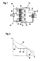
- a known power plant which shown in Figure 1 and there as a whole with 10 includes a steam generating stage 12 and a turbine stage 14.
- the steam generating stage 12 includes a preheater 16, a Evaporator 18 and a superheater 20th preheater 16, evaporator 18 and Superheater 20 each have heat exchanger surfaces 22, where water or steam can absorb heat for preheating (in the preheater 16), to Evaporation (in the evaporator 18) or overheating of the steam (im Superheater 20).
- An outlet 23 of the superheater 20, which has an overheated outlet Steam is coupled to a steam turbine 24, which has a generator 26 drives.
- a relaxation of the steam takes place and the corresponding mechanical energy is used to generate electrical Electricity used.
- a line 28 leads to an inlet 30 of the preheater 16.
- the input 30 is an input for feedwater. This feedwater is preheated in the preheater 16.
- a heat exchanger 32 is arranged in line 28 .
- the (liquid) Feedwater is conveyed via a pump 34 to the preheater 16.
- An output 36 of the preheater 16 is connected to an inlet 38 of the evaporator 18 connected. At the entrance 38, the evaporator 18 is preheated Water provided.
- An output 40 of the evaporator 18 is connected to an input 42 of the superheater 20 connected. About the output 40, the superheater 20 steam for overheating provided in the superheater 20.
- the steam generating stage 12 and the turbine stage 14 are connected via a Water / steam cycle 44 connected together.
- a working medium circuit 46 is provided, wherein the preheater 16, the evaporator 18 and the superheater 20 to a working medium guide 48th are coupled.
- a heating source 50 is arranged, in which the guided in the working medium circuit 46 working medium how air is heatable.
- the working medium is over the heating source 50 solar or heated by combustion processes.
- This in the heating source 50 heated working fluid is an input 52 of the Superheater 20 is supplied, in order for the overheating of the through Superheater to carry out 20 carried steam. After flowing through the Superheater 20 flows through the correspondingly cooled working fluid Evaporator 18.
- the working medium causes the evaporation of the water. From the evaporator 18 it is then the preheater 16 supplied. There, the residual heat of the evaporator 18 is used, to preheat input water injected via input 30.
- the working medium is then to the heating source 50 for heating recycled.
- Such a power plant scheme is for example in the figure 6 of the article "An Update on Solar Central Receiver Systems, Projects, and Technologies "by M. Romero et al. in Transactions of the ASME, Vol. 124, May 2002, pages 98-108.
- the lower curve 58 corresponds to water / steam. It essentially comprises one linear preheating area for passing through the preheater 16, a essentially temperature-independent evaporation zone for evaporation in the evaporator 18 and an overheating area 64, which in the is substantially linear, generated for the overheating of the evaporator 18 Steam in the superheater 20.
- the pinch point is defined as the enthalpy at which the curves 56 and 58 have the minimum distance. It is designated 66 in FIG. This pinch point sets the inlet temperature of the working medium at the entrance 52 of the superheater 20 and the outlet temperature at the preheater 16 fixed. There due to the evaporator 18, the temperature for the curve 56 at the pinch point 66 is relatively high, the inlet temperature at the inlet 52 must be corresponding be chosen high.
- the evaporator in a steam generation stage at least separated from the superheater so as to Pinch point problem to work around.
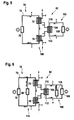
- a first embodiment of the solution according to the invention comprises a steam generating stage 68 a working medium circuit 70.
- a superheater 74 In the corresponding Schwarzmedium exchange 72 is a superheater 74 and this respect downstream of the working medium guide a preheater 76 is arranged.
- a heating source 78 is arranged in the working medium circuit 70.
- the heat source 78 which is a radiation receiver such as an absorber for solar radiation or a volumetric Receiver can act, the working fluid is heated, wherein the working medium as a "secondary" heat source then turn the superheater 74 and the preheater 76 heats.
- Heat accumulator 80 is arranged to store heat.
- Heat storage 80 can be used as a working medium, for example, bulk material storage in air or sand storage.
- the superheater 74 and the preheater 76 is a first heating system 82nd formed over which can heat water / steam.
- the preheater 76 heats Feed water before and the superheater 74 superheats steam, which of a Evaporator 84 was generated.
- the evaporator 84 itself is at a second Heating system 86 coupled or is part of this heating system. This second Heating system 86 itself has a heating source. This heat source heats directly or indirectly the evaporator 84 to get out of the preheater 76 preheated by the preheater Water to produce steam.
- the evaporator 84 is direct solar heated, d. H. he is provided with appropriate absorber surfaces on the concentrated solar radiation is directed. It then takes a heating of the water flowing through the evaporator, which for vapor formation leads.
- the evaporator 84 thus represents a kind of "secondary" heat source.
- the second heating system 86 is independent of the heating with respect to the heating first heating system 82 for heating the superheater 74 and with respect to the heating decoupled from the superheater 74.
- an evaporator path 88 of the second heating system 86 can be separated from the working medium cycle 70.
- By the separation of Evaporation and overheating in two heating systems 86, 82 can be the corresponding Adjust temperature levels separately. This can be a Achieve overall efficiency improvements of 10% or more can.
- the overall efficiency refers to a turbine-stage power plant.
- the turbine stage in the embodiment according to FIG. 3 is basically the same as described above in connection with FIG.
- the working medium can be at a lower temperature in the superheater 74th inject. This, in turn, makes the material requirements for the superheater 74 reduced, so that produce this component at a lower cost leaves and according to the maintenance is also reduced.
- FIG. 4 shows a corresponding T-H diagram for the power plant concept shown in FIG.
- the curve 90 is the T-H curve for air as the working medium, which is heated in the first heating system 82.
- the underlying one Curve 92 is the water / steam curve for passing through the first heating system 82 of the steam generating stage 68.
- This curve 92 has a preheating area 94 and an overheating area 96.
- the evaporation area as shown in Figure 2 by the reference numeral 62, "missing" here, since the evaporator 84 is not included in the first heating system 82, but is coupled to the second heating system 86.
- the pinch point is thus not at a transition between the preheating area 94 and an evaporation area (since such an evaporation area not available). This gives the possibility according to the inlet temperature for working medium (point e) in comparison to lower the conventional concept of Figure 1.
- the pinch point is predeterminable and is just chosen so that on a correspondingly lower Temperature working medium the superheater 74 can be fed.
- Pinch Point 98 is at the maximum transferable heat, d. H. in the highest temperature.
- the second heating system 86 By separating the heating of the superheater 74 (together with the Preheater 76) opposite the evaporator 84 in a first heating system 82nd and in a second heating system 86 is the "secondary" heat source, by means of which directly transfers heat to water / steam, in the two heating systems separated.
- working fluid transfers into the superheater 74 heat to the overheated steam. This working medium is not in thermal contact with the evaporator 84.
- the evaporator 84 itself is heated by a separate heat source.
- both heating systems 82 and 86 the same primary heating source, such as solar radiation.
- the evaporator 84 may for example also a tower, with concentrated solar radiation for the Heating ensures. It is also possible that the evaporator 84 by means of combustion processes is heated.
- the first heating system 82 may be solar heated or burned be heated.
- the heating source 78 itself may be, for example act a volumetric receiver.
- the preheater 76 is in FIG the first heating system 82 incorporated, d. H. the preheater 76 is by means of Residual heat of the superheater 74 heated. But it is also possible that the preheater is integrated into the second heating system 86 and thereby residual heat the evaporator 84 is heated (not shown in the figure).
- a second embodiment of a steam generation stage according to the invention which is designated as 100 in Figure 5 as a whole, is the Working medium circuit 70 basically the same structure, as related described with the first embodiment 68. It will therefore, the same reference numerals used here. (In the embodiment according to Figure 5, no heat storage is shown.) Accordingly, the first heating system 82 is the same.
- a second heating system 102 includes an evaporator 104, which in a Circuit 106 is arranged for heat transfer medium.
- this Circuit 106 is the heat transfer medium, such as thermal oil, guided.
- the circuit 106 includes a heating source 108, in which the Heat transfer medium is heated. It then becomes an input 110 supplied to the evaporator 104, wherein this input 110 is an input for Heat transfer medium is. From an exit 112 is cooled Heat transfer medium returned to the heat source 108.
- the evaporator 104 is the heat transfer medium heat in the Evaporator 104 injected water to generate steam.
- the heating source 108 may be solar heated.
- a heat storage 116 is arranged in the circuit 106 parallel to the input 110th and the output 112 of the evaporator 104.
- This heat storage 116 can be heated heat transfer medium caching and failing heat source 108 or at reduced heat output of the heating source 108 can be the evaporator 104 heated heat transfer medium from the heat storage 116th respectively.
- the heat storage 116 may be, for example, an oil reservoir, Concrete storage or salt storage act. When as a heat transfer medium Salt is used, then this salt in the heat storage 116 are stored directly.
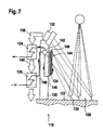
- a Tower 120 is provided, at the distance to the bottom 122, an evaporator 124 is sitting.
- the evaporator 124 includes, for example, absorber tubes, directed to the concentrated solar radiation 126.
- Concentrating the Solar radiation is a heliostat field 128 with a plurality of heliostats 130 provided. These direct concentrated solar radiation onto the evaporator 124th
- an air receiver is still seated 132, is also directed to the concentrated solar radiation.
- air is heated as a working medium.
- Hot air is passed from the air receiver 132 to a superheater 134. This is indicated by an arrow 136. From the superheater 134 is cooled Air is guided to a preheater 138, which is indicated by an arrow 140 is.
- the exemplary embodiment according to FIG. 7 corresponds to that in FIG. 3 shown principle (without heat storage 80):
- the evaporator 124 corresponds the evaporator 84 according to FIG. 3.
- the air receiver 132 represents the (secondary) Heat source 78 according to Figure 3 is.
- both heat sources are solar heated be arranged spatially next to each other.
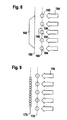
- water / steam is in a plurality guided by spaced, juxtaposed tubes.
- These Tubes are designed as absorber tubes, which with concentrated solar radiation 154 be charged.
- These tubes 152 are part of an evaporator or preheater. Between adjacent tubes 156, 158 is a Free space 160 formed by the solar radiation 154 can penetrate.
- Behind the Pipe row is a heating area 162 for a superheater or preheater arranged. In this heating area, the working medium is like air heated, which in turn supplied to the superheater for overheating becomes.
- the heating region 162 may be, for example, a volumetric Receiver be formed.
- the heating area 164 of the respective pipes 154 is formed accordingly by an absorber surface.
- the heating areas 162 and 164 lie side by side in a loading area for concentrated solar radiation 154. This forms an integrated receiver, d. H. an integrated heating source for the first heating system 82 and second heating system 86 and 102, respectively.
- This integrated receiver has a first level 166 as a heating source for the Evaporator (for example, according to the heat source 108 of FIG 6) and a second level 168, for example, corresponding to the heating source 78 on.
- a second pipe register 172 is arranged, which serves as a heat source for a superheater.
- first pipe register 170 the pipes are spaced.
- second pipe register 172 adjacent tubes preferably abut each other directly.
Applications Claiming Priority (2)
| Application Number | Priority Date | Filing Date | Title |
|---|---|---|---|
| DE10346255A DE10346255A1 (de) | 2003-09-25 | 2003-09-25 | Verfahren zur Erzeugung von überhitztem Dampf, Dampferzeugungsstufe für ein Kraftwerk und Kraftwerk |
| DE10346255 | 2003-09-25 |
Publications (2)
| Publication Number | Publication Date |
|---|---|
| EP1519108A1 true EP1519108A1 (de) | 2005-03-30 |
| EP1519108B1 EP1519108B1 (de) | 2011-12-07 |
Family
ID=34178041
Family Applications (1)
| Application Number | Title | Priority Date | Filing Date |
|---|---|---|---|
| EP04018433A Not-in-force EP1519108B1 (de) | 2003-09-25 | 2004-08-04 | Verfahren zur Erzeugung von überhitztem Dampf, Dampferzeugungsstufe für ein Kraftwerk und Kraftwerk |
Country Status (3)
| Country | Link |
|---|---|
| EP (1) | EP1519108B1 (es) |
| AT (1) | ATE536517T1 (es) |
| DE (1) | DE10346255A1 (es) |
Cited By (29)
| Publication number | Priority date | Publication date | Assignee | Title |
|---|---|---|---|---|
| WO2008109746A2 (en) * | 2007-03-06 | 2008-09-12 | Solar & Environmental Technologies Corp. | Solar energy system |
| GR20080100375A (el) * | 2008-06-02 | 2010-01-27 | Εστια Συμβουλοι Και Μηχανικοι Α.Ε. | Συνδυασμενος κυκλος παραγωγης ηλεκτρικης ενεργειας και θερμοτητας απο ηλιακη ενεργεια και καυση βιομαζας |
| EP2161525A1 (de) * | 2008-09-08 | 2010-03-10 | Balcke-Dürr GmbH | Wärmetauscher in Modulbauweise |
| WO2010031375A2 (de) * | 2008-09-19 | 2010-03-25 | Ecoenergy Gesellschaft Für Energie- Und Umwelttechnik Mbh | Verfahren zur überhitzung von dampf |
| WO2010052172A1 (de) * | 2008-11-07 | 2010-05-14 | Deutsches Zentrum für Luft- und Raumfahrt e.V. | Verfahren zur entsalzung von salzhaltigem wasser |
| WO2011006831A2 (de) | 2009-07-13 | 2011-01-20 | Deutsches Zentrum für Luft- und Raumfahrt e.V. | Solarthermisches kraftwerk |
| WO2011028633A1 (en) * | 2009-09-03 | 2011-03-10 | Pratt & Whitney Rocketdyne, Inc. | Solar desalinization plant |
| CN102003696A (zh) * | 2010-11-17 | 2011-04-06 | 东方锅炉(集团)股份有限公司 | 分级腔体式太阳能吸热器以及换热系统 |
| CN102007292A (zh) * | 2008-04-16 | 2011-04-06 | 阿尔斯托姆科技有限公司 | 太阳能热电设备 |
| WO2011053863A2 (en) | 2009-10-30 | 2011-05-05 | Areva Solar, Inc. | Dual fluid circuit system for generating a vaporous working fluid using solar energy |
| ITBS20090209A1 (it) * | 2009-11-17 | 2011-05-18 | Turboden Srl | Impianto per la produzione di energia elettrica basato su ciclo rankine organico |
| ITBS20100095A1 (it) * | 2010-05-13 | 2011-11-14 | Turboden Srl | Impianto orc ad alta temperatura ottimizzato |
| EP2410177A1 (en) * | 2009-03-20 | 2012-01-25 | Abengoa Solar New Technologies, S.A. | Air- and steam-technology combined solar plant |
| WO2012025284A1 (de) * | 2010-08-27 | 2012-03-01 | Thyssenkrupp Xervon Energy Gmbh | Verfahren zum betreiben einer dampfturbine eines solarthermischen kraftwerkes sowie kesselanlage zur durchführung des verfahrens |
| WO2011138215A3 (de) * | 2010-05-06 | 2012-03-15 | Siemens Aktiengesellschaft | Solarer kraftwerksteil einer solarthermischen kraftwerksanlage und solarthermische kraftwerksanlage mit sonnenkollektorflächen für wärmeträgermedium und arbeitsmedium |
| WO2011104328A3 (de) * | 2010-02-26 | 2012-03-15 | Siemens Aktiengesellschaft | Vorrichtung und verfahren zur erzeugen von überhitztem wasserdampf mittels solar-energie basierend auf dem naturumlauf-konzept sowie verwendung des überhitzten wasserdampfs |
| WO2011104325A3 (de) * | 2010-02-26 | 2012-03-15 | Siemens Aktiengesellschaft | Vorrichtung und verfahren zur erzeugen von überhitztem wasserdampf mittels solar-energie basierend auf dem zwangsdurchlauf-konzept sowie verwendung des überhitzten wasserdampfs |
| WO2012041989A1 (de) * | 2010-09-30 | 2012-04-05 | Siemens Aktiengesellschaft | Vorrichtung und verfahren zum erzeugen von überhitztem wasserdampf mittels solar-energie basierend auf dem zwangsdurchlauf-konzept mit helikaler wasser/wasserdampf-führung sowie verwendung des überhitzten wasserdampfs |
| WO2012050788A3 (en) * | 2010-09-30 | 2012-07-19 | Dow Global Technologies Llc | Apparatus and process for producing superheated steam from a concentrating solar power plant |
| EP2487338A1 (en) * | 2011-02-11 | 2012-08-15 | Alstom Technology Ltd | Solar thermal power plant |
| CN102859190A (zh) * | 2010-04-19 | 2013-01-02 | 道康宁公司 | 太阳能热力发电设备 |
| US8378280B2 (en) | 2007-06-06 | 2013-02-19 | Areva Solar, Inc. | Integrated solar energy receiver-storage unit |
| WO2013056752A1 (de) * | 2011-10-19 | 2013-04-25 | Horst Schierack | Solarthermisches kraftwerk sowie verfahren zum betreiben eines solarthermischen kraftwerks |
| US8739512B2 (en) | 2007-06-06 | 2014-06-03 | Areva Solar, Inc. | Combined cycle power plant |
| US8807128B2 (en) | 2007-08-27 | 2014-08-19 | Areva Solar, Inc. | Linear fresnel solar arrays |
| WO2013135761A3 (de) * | 2012-03-16 | 2014-09-25 | Siemens Aktiengesellschaft | Leistungsregelung und/oder frequenzregelung bei einem solarthermischen dampfkraftwerk |
| US9022020B2 (en) | 2007-08-27 | 2015-05-05 | Areva Solar, Inc. | Linear Fresnel solar arrays and drives therefor |
| EP2279334A4 (en) * | 2008-03-12 | 2017-10-25 | Greelec Ab | Thermal solar power plant |
| CN109737620A (zh) * | 2018-12-18 | 2019-05-10 | 南京天创电子技术有限公司 | 一种太阳能加热供热管网蒸汽和冷凝水的系统及方法 |
Families Citing this family (9)
| Publication number | Priority date | Publication date | Assignee | Title |
|---|---|---|---|---|
| CN101354021B (zh) * | 2007-07-27 | 2010-06-02 | 张文广 | 太阳能热复合发电系统 |
| DE102009038446B4 (de) * | 2009-08-21 | 2016-10-06 | Flagsol Gmbh | Solarthermisches Kraftwerk mit Wärmetauscher in der Speisewasservorwärmstrecke |
| DE102011004271A1 (de) * | 2011-02-17 | 2012-08-23 | Siemens Aktiengesellschaft | Durchlaufdampferzeuger für die indirekte Verdampfung insbesondere in einem Solarturm-Kraftwerk |
| DE102011004270A1 (de) * | 2011-02-17 | 2012-08-23 | Siemens Aktiengesellschaft | Durchlaufdampferzeuger für die indirekte Verdampfung insbesondere in einem Solarturm-Kraftwerk |
| DE102011004272A1 (de) * | 2011-02-17 | 2012-08-23 | Siemens Aktiengesellschaft | Durchlaufverdampfer |
| DE102011004279A1 (de) * | 2011-02-17 | 2012-08-23 | Siemens Aktiengesellschaft | Dampferzeuger für solarthermisches Kraftwerk |
| DE102011004276A1 (de) * | 2011-02-17 | 2012-08-23 | Siemens Aktiengesellschaft | Durchlaufverdampfer |
| DE102012006729A1 (de) | 2012-04-02 | 2013-10-02 | Hans-Malte Rombrecht | Solarthermisches Kraftwerk mit verbesserter Wirtschaftlichkeit |
| DE102012023898A1 (de) * | 2012-12-07 | 2014-06-12 | Man Diesel & Turbo Se | Verfahren zum Betreiben einer Anlage zur Erzeugung mechanischer und/oder elektrischer Energie |
Citations (4)
| Publication number | Priority date | Publication date | Assignee | Title |
|---|---|---|---|---|
| FR2438804A1 (fr) * | 1978-10-10 | 1980-05-09 | Babcock & Wilcox Co | Chaudiere solaire |
| DE4126038A1 (de) * | 1991-08-06 | 1993-02-11 | Siemens Ag | Gas- und dampfturbinenkraftwerk mit einem solarbeheizten dampferzeuger |
| US5619933A (en) | 1992-09-17 | 1997-04-15 | Ansaldo Volund A/S | Method and plant for producing high steam temperatures when burning problematic fuels |
| DE10128562C1 (de) * | 2001-06-13 | 2003-01-09 | Deutsch Zentr Luft & Raumfahrt | Solarthermisches Kraftwerk und Verfahren zur Umwandlung von thermischer Energie in mechanische/elektrische Energie in einem solarthermischen Kraftwerk |
Family Cites Families (7)
| Publication number | Priority date | Publication date | Assignee | Title |
|---|---|---|---|---|
| US4076025A (en) * | 1976-11-22 | 1978-02-28 | Parker Louis W | Solar steam boiler |
| JPS5634061A (en) * | 1979-08-28 | 1981-04-06 | Agency Of Ind Science & Technol | Superheater for steam for absorbing solar heat |
| JPS5634060A (en) * | 1979-08-28 | 1981-04-06 | Agency Of Ind Science & Technol | Superheater for steam for absorbing solar heat |
| AU1425295A (en) * | 1994-10-19 | 1996-05-15 | Kazukimi Hiratsuka | Ball worm gear |
| DE10144841B9 (de) * | 2001-09-06 | 2004-10-21 | Deutsches Zentrum für Luft- und Raumfahrt e.V. | Solarthermisches Gas- und Dampfkraftwerk und Verfahren zur Umwandlung von thermischer Energie in elektrische Energie |
| DE10149806C2 (de) * | 2001-10-09 | 2003-11-13 | Deutsch Zentr Luft & Raumfahrt | Solarturmkraftwerk |
| DE10152971C1 (de) * | 2001-10-19 | 2002-12-05 | Deutsch Zentr Luft & Raumfahrt | Solarthermisches Kraftwerk und Regelungsverfahren für ein solarthermisches Kraftwerk |
-
2003
- 2003-09-25 DE DE10346255A patent/DE10346255A1/de not_active Withdrawn
-
2004
- 2004-08-04 AT AT04018433T patent/ATE536517T1/de active
- 2004-08-04 EP EP04018433A patent/EP1519108B1/de not_active Not-in-force
Patent Citations (4)
| Publication number | Priority date | Publication date | Assignee | Title |
|---|---|---|---|---|
| FR2438804A1 (fr) * | 1978-10-10 | 1980-05-09 | Babcock & Wilcox Co | Chaudiere solaire |
| DE4126038A1 (de) * | 1991-08-06 | 1993-02-11 | Siemens Ag | Gas- und dampfturbinenkraftwerk mit einem solarbeheizten dampferzeuger |
| US5619933A (en) | 1992-09-17 | 1997-04-15 | Ansaldo Volund A/S | Method and plant for producing high steam temperatures when burning problematic fuels |
| DE10128562C1 (de) * | 2001-06-13 | 2003-01-09 | Deutsch Zentr Luft & Raumfahrt | Solarthermisches Kraftwerk und Verfahren zur Umwandlung von thermischer Energie in mechanische/elektrische Energie in einem solarthermischen Kraftwerk |
Non-Patent Citations (4)
| Title |
|---|
| GEYER UND H KLAISS M: "194 MW Solarstrom mit Rinnenkollektoren", BWK BRENNSTOFF WARME KRAFT, VDI VERLAG GMBH. DUSSELDORF, DE, vol. 41, no. 6, June 1989 (1989-06-01), pages 288 - 295, XP002124842, ISSN: 0006-9612 * |
| VON H. PRICE ET AL.: "Advances in Parabolic Trough Solar Power Technology", JOURNAL OF SOLAR ENERGY ENGINEERING, vol. 124, May 2002 (2002-05-01), pages 109 - 125 |
| VON M. GEYER; H. KLAISS: "194 MW Solarstrom mit Rinnenkollektoren", BWK BD., vol. 41, no. 6, 1989 |
| VON M. ROMERO ET AL.: "An Update on Solar Central Receiver Systems, Projekts, and Technologies", TRANSACTIONS OF THE ASME, vol. 124, May 2002 (2002-05-01), pages 98 - 108 |
Cited By (50)
| Publication number | Priority date | Publication date | Assignee | Title |
|---|---|---|---|---|
| WO2008109746A3 (en) * | 2007-03-06 | 2011-12-08 | Solar & Environmental Technologies Corp. | Solar energy system |
| WO2008109746A2 (en) * | 2007-03-06 | 2008-09-12 | Solar & Environmental Technologies Corp. | Solar energy system |
| US8739512B2 (en) | 2007-06-06 | 2014-06-03 | Areva Solar, Inc. | Combined cycle power plant |
| US8378280B2 (en) | 2007-06-06 | 2013-02-19 | Areva Solar, Inc. | Integrated solar energy receiver-storage unit |
| US9022020B2 (en) | 2007-08-27 | 2015-05-05 | Areva Solar, Inc. | Linear Fresnel solar arrays and drives therefor |
| US8807128B2 (en) | 2007-08-27 | 2014-08-19 | Areva Solar, Inc. | Linear fresnel solar arrays |
| EP2279334A4 (en) * | 2008-03-12 | 2017-10-25 | Greelec Ab | Thermal solar power plant |
| CN102007292A (zh) * | 2008-04-16 | 2011-04-06 | 阿尔斯托姆科技有限公司 | 太阳能热电设备 |
| CN102007292B (zh) * | 2008-04-16 | 2014-03-12 | 阿尔斯托姆科技有限公司 | 太阳能热电设备 |
| GR20080100375A (el) * | 2008-06-02 | 2010-01-27 | Εστια Συμβουλοι Και Μηχανικοι Α.Ε. | Συνδυασμενος κυκλος παραγωγης ηλεκτρικης ενεργειας και θερμοτητας απο ηλιακη ενεργεια και καυση βιομαζας |
| WO2010025960A2 (de) * | 2008-09-08 | 2010-03-11 | Balcke-Dürr GmbH | Wärmetauscher in modulbauweise |
| CN102149999B (zh) * | 2008-09-08 | 2012-11-14 | 巴尔克有限公司 | 模块化构造的热交换器 |
| WO2010025960A3 (de) * | 2008-09-08 | 2010-06-17 | Balcke-Dürr GmbH | Wärmetauscher in modulbauweise |
| US8708035B2 (en) | 2008-09-08 | 2014-04-29 | Balcke-Dürr GmbH | Heat exchanger in a modular construction |
| EP2161525A1 (de) * | 2008-09-08 | 2010-03-10 | Balcke-Dürr GmbH | Wärmetauscher in Modulbauweise |
| WO2010031375A3 (de) * | 2008-09-19 | 2011-09-29 | Ecoenergy Gesellschaft Für Energie- Und Umwelttechnik Mbh | Verfahren zur überhitzung von dampf |
| WO2010031375A2 (de) * | 2008-09-19 | 2010-03-25 | Ecoenergy Gesellschaft Für Energie- Und Umwelttechnik Mbh | Verfahren zur überhitzung von dampf |
| WO2010052172A1 (de) * | 2008-11-07 | 2010-05-14 | Deutsches Zentrum für Luft- und Raumfahrt e.V. | Verfahren zur entsalzung von salzhaltigem wasser |
| EP2410177A4 (en) * | 2009-03-20 | 2014-05-28 | Abengoa Solar New Tech Sa | COMBINED SOLAR INSTALLATION WITH AIR-VAPOR TECHNOLOGY |
| EP2410177A1 (en) * | 2009-03-20 | 2012-01-25 | Abengoa Solar New Technologies, S.A. | Air- and steam-technology combined solar plant |
| WO2011006831A2 (de) | 2009-07-13 | 2011-01-20 | Deutsches Zentrum für Luft- und Raumfahrt e.V. | Solarthermisches kraftwerk |
| DE102009033951A9 (de) | 2009-07-13 | 2011-06-09 | Deutsches Zentrum für Luft- und Raumfahrt e.V. | Solarthermisches Kraftwerk |
| DE102009033951A1 (de) | 2009-07-13 | 2011-01-20 | Deutsches Zentrum für Luft- und Raumfahrt e.V. | Solarthermisches Kraftwerk |
| WO2011028633A1 (en) * | 2009-09-03 | 2011-03-10 | Pratt & Whitney Rocketdyne, Inc. | Solar desalinization plant |
| US8246787B2 (en) | 2009-09-03 | 2012-08-21 | Pratt & Whitney Rockedyne, Inc. | Solar desalinization plant |
| WO2011053863A2 (en) | 2009-10-30 | 2011-05-05 | Areva Solar, Inc. | Dual fluid circuit system for generating a vaporous working fluid using solar energy |
| WO2011053863A3 (en) * | 2009-10-30 | 2012-05-31 | Areva Solar, Inc. | Dual fluid circuit system for generating a vaporous working fluid using solar energy |
| CN102753823A (zh) * | 2009-10-30 | 2012-10-24 | 阿海珐太阳能公司 | 用于利用太阳能产生蒸气状工作流体的双流体线路系统 |
| ITBS20090209A1 (it) * | 2009-11-17 | 2011-05-18 | Turboden Srl | Impianto per la produzione di energia elettrica basato su ciclo rankine organico |
| WO2011104325A3 (de) * | 2010-02-26 | 2012-03-15 | Siemens Aktiengesellschaft | Vorrichtung und verfahren zur erzeugen von überhitztem wasserdampf mittels solar-energie basierend auf dem zwangsdurchlauf-konzept sowie verwendung des überhitzten wasserdampfs |
| WO2011104328A3 (de) * | 2010-02-26 | 2012-03-15 | Siemens Aktiengesellschaft | Vorrichtung und verfahren zur erzeugen von überhitztem wasserdampf mittels solar-energie basierend auf dem naturumlauf-konzept sowie verwendung des überhitzten wasserdampfs |
| US20130086904A1 (en) * | 2010-04-19 | 2013-04-11 | Dave Bent | Solar Thermal Power Plant |
| CN102859190A (zh) * | 2010-04-19 | 2013-01-02 | 道康宁公司 | 太阳能热力发电设备 |
| WO2011138215A3 (de) * | 2010-05-06 | 2012-03-15 | Siemens Aktiengesellschaft | Solarer kraftwerksteil einer solarthermischen kraftwerksanlage und solarthermische kraftwerksanlage mit sonnenkollektorflächen für wärmeträgermedium und arbeitsmedium |
| CN102884317A (zh) * | 2010-05-06 | 2013-01-16 | 西门子公司 | 太阳能热电站设备的太阳能电站部分和具有用于载热介质和工质的太阳能收集器面的太阳能热电站设备 |
| US9279347B2 (en) | 2010-05-13 | 2016-03-08 | Turboden S.R.L. | High temperature ORC system |
| ITBS20100095A1 (it) * | 2010-05-13 | 2011-11-14 | Turboden Srl | Impianto orc ad alta temperatura ottimizzato |
| WO2011141942A1 (en) | 2010-05-13 | 2011-11-17 | Turboden S.R.L. | Improved high temperature orc system |
| WO2012025284A1 (de) * | 2010-08-27 | 2012-03-01 | Thyssenkrupp Xervon Energy Gmbh | Verfahren zum betreiben einer dampfturbine eines solarthermischen kraftwerkes sowie kesselanlage zur durchführung des verfahrens |
| WO2012041989A1 (de) * | 2010-09-30 | 2012-04-05 | Siemens Aktiengesellschaft | Vorrichtung und verfahren zum erzeugen von überhitztem wasserdampf mittels solar-energie basierend auf dem zwangsdurchlauf-konzept mit helikaler wasser/wasserdampf-führung sowie verwendung des überhitzten wasserdampfs |
| WO2012050788A3 (en) * | 2010-09-30 | 2012-07-19 | Dow Global Technologies Llc | Apparatus and process for producing superheated steam from a concentrating solar power plant |
| CN103477033A (zh) * | 2010-09-30 | 2013-12-25 | 陶氏环球技术有限责任公司 | 用于从聚光太阳能设备产生过热蒸汽的方法和设备 |
| US9389002B2 (en) | 2010-09-30 | 2016-07-12 | Dow Global Technologies Llc | Process for producing superheated steam from a concentrating solar power plant |
| CN102003696A (zh) * | 2010-11-17 | 2011-04-06 | 东方锅炉(集团)股份有限公司 | 分级腔体式太阳能吸热器以及换热系统 |
| WO2012107478A1 (en) * | 2011-02-11 | 2012-08-16 | Alstom Technology Ltd | Solar thermal power plant |
| EP2487338A1 (en) * | 2011-02-11 | 2012-08-15 | Alstom Technology Ltd | Solar thermal power plant |
| WO2013056752A1 (de) * | 2011-10-19 | 2013-04-25 | Horst Schierack | Solarthermisches kraftwerk sowie verfahren zum betreiben eines solarthermischen kraftwerks |
| WO2013135761A3 (de) * | 2012-03-16 | 2014-09-25 | Siemens Aktiengesellschaft | Leistungsregelung und/oder frequenzregelung bei einem solarthermischen dampfkraftwerk |
| CN109737620A (zh) * | 2018-12-18 | 2019-05-10 | 南京天创电子技术有限公司 | 一种太阳能加热供热管网蒸汽和冷凝水的系统及方法 |
| CN109737620B (zh) * | 2018-12-18 | 2024-02-09 | 南京天创电子技术有限公司 | 一种太阳能加热供热管网蒸汽和冷凝水的系统及方法 |
Also Published As
| Publication number | Publication date |
|---|---|
| EP1519108B1 (de) | 2011-12-07 |
| DE10346255A1 (de) | 2005-04-28 |
| ATE536517T1 (de) | 2011-12-15 |
Similar Documents
| Publication | Publication Date | Title |
|---|---|---|
| EP1519108B1 (de) | Verfahren zur Erzeugung von überhitztem Dampf, Dampferzeugungsstufe für ein Kraftwerk und Kraftwerk | |
| EP2521861B1 (de) | Solarthermisches kraftwerk mit indirekter verdampfung und verfahren zum betrieb eines solchen solarthermischen kraftwerks | |
| EP2419634B1 (de) | Dampfkraftwerk mit solarkollektoren | |
| EP0750730B1 (de) | Verfahren zur solaren Dampferzeugung | |
| WO2008067855A2 (de) | Verfahren und vorrichtung zur erhöhung von leistung und wirkungsgrad eines orc-kraftwerkprozesses | |
| DE102010041903B4 (de) | Durchlaufdampferzeuger mit integriertem Zwischenüberhitzer | |
| WO2008113482A2 (de) | Verfahren und vorrichtung zur befeuerten zwischenüberhitzung bei solarer direktverdampfung in einem solarthermischen kraftwerk | |
| DE10128562C1 (de) | Solarthermisches Kraftwerk und Verfahren zur Umwandlung von thermischer Energie in mechanische/elektrische Energie in einem solarthermischen Kraftwerk | |
| DE102007013430A1 (de) | Solarthermisches Kraftwerk und Verfahren zum Betreiben eines solarthermischen Kraftwerks | |
| DE10144841C1 (de) | Solarthermisches Gas- und Dampfkraftwerk und Verfahren zur Umwandlung von thermischer Energie in elektrische Energie | |
| EP1794495B1 (de) | Fossil beheizter durchlaufdampferzeuger | |
| DE10152971C1 (de) | Solarthermisches Kraftwerk und Regelungsverfahren für ein solarthermisches Kraftwerk | |
| DE10152968C1 (de) | Solarthermisches Kraftwerk und Verfahren zum Betreiben eines solarthermischen Kraftwerks | |
| DE102010040208B4 (de) | Solarthermische Durchlaufverdampfer-Heizfläche mit lokaler Querschnittsverengung an ihrem Eintritt | |
| EP3017152A2 (de) | Gas-und-dampf-kombikraftwerk mit einem abhitzedampferzeuger und einer brennstoffvorwärmung | |
| DE3020297A1 (de) | Anlage zur erzeugung von ueberhitztem prozessdampf aus salzhaltigem rohwasser | |
| DE102013101648A1 (de) | Verfahren und Vorrichtung zur Speicherung und Übertragung von thermischer Energie | |
| WO2012028512A2 (de) | Solarthermischer durchlaufdampferzeuger für die direktverdampfung insbesondere in einem solarturm-kraftwerk | |
| WO2013034139A1 (de) | Verfahren und vorrichtung zur speicherung und rückgewinnung von thermischer energie | |
| DE102005031023B3 (de) | Solarkollektorfeld | |
| WO2012028517A2 (de) | Solarthermischer durchlaufverdampfer | |
| EP2177757A1 (de) | Verfahren und Vorrichtung zur Zwischenüberhitzung mit Sattdampf bei solarer Direktverdampfung in einem solarthermischen Kraftwerk | |
| WO2012028514A2 (de) | Solarthermischer absorber zur direktverdampfung, insbesondere in einem solarturm-kraftwerk | |
| EP4056668A1 (de) | Verfahren und anlage zum steamcracken | |
| AT150463B (de) | Verfahren zur Erzeugung von Dampf und Einrichtungen zu seiner Durchführung. |
Legal Events
| Date | Code | Title | Description |
|---|---|---|---|
| PUAI | Public reference made under article 153(3) epc to a published international application that has entered the european phase |
Free format text: ORIGINAL CODE: 0009012 |
|
| AK | Designated contracting states |
Kind code of ref document: A1 Designated state(s): AT BE BG CH CY CZ DE DK EE ES FI FR GB GR HU IE IT LI LU MC NL PL PT RO SE SI SK TR |
|
| AX | Request for extension of the european patent |
Extension state: AL HR LT LV MK |
|
| 17P | Request for examination filed |
Effective date: 20050705 |
|
| AKX | Designation fees paid |
Designated state(s): AT BE BG CH CY CZ DE DK EE ES FI FR GB GR HU IE IT LI LU MC NL PL PT RO SE SI SK TR |
|
| RAP1 | Party data changed (applicant data changed or rights of an application transferred) |
Owner name: DEUTSCHES ZENTRUM FUER LUFT- UND RAUMFAHRT E.V. |
|
| 17Q | First examination report despatched |
Effective date: 20081014 |
|
| GRAP | Despatch of communication of intention to grant a patent |
Free format text: ORIGINAL CODE: EPIDOSNIGR1 |
|
| GRAS | Grant fee paid |
Free format text: ORIGINAL CODE: EPIDOSNIGR3 |
|
| GRAA | (expected) grant |
Free format text: ORIGINAL CODE: 0009210 |
|
| AK | Designated contracting states |
Kind code of ref document: B1 Designated state(s): AT BE BG CH CY CZ DE DK EE ES FI FR GB GR HU IE IT LI LU MC NL PL PT RO SE SI SK TR |
|
| REG | Reference to a national code |
Ref country code: GB Ref legal event code: FG4D Free format text: NOT ENGLISH |
|
| REG | Reference to a national code |
Ref country code: CH Ref legal event code: EP |
|
| REG | Reference to a national code |
Ref country code: IE Ref legal event code: FG4D Free format text: LANGUAGE OF EP DOCUMENT: GERMAN |
|
| REG | Reference to a national code |
Ref country code: DE Ref legal event code: R096 Ref document number: 502004013126 Country of ref document: DE Effective date: 20120216 |
|
| REG | Reference to a national code |
Ref country code: NL Ref legal event code: VDEP Effective date: 20111207 |
|
| PG25 | Lapsed in a contracting state [announced via postgrant information from national office to epo] |
Ref country code: NL Free format text: LAPSE BECAUSE OF FAILURE TO SUBMIT A TRANSLATION OF THE DESCRIPTION OR TO PAY THE FEE WITHIN THE PRESCRIBED TIME-LIMIT Effective date: 20111207 Ref country code: SI Free format text: LAPSE BECAUSE OF FAILURE TO SUBMIT A TRANSLATION OF THE DESCRIPTION OR TO PAY THE FEE WITHIN THE PRESCRIBED TIME-LIMIT Effective date: 20111207 Ref country code: SE Free format text: LAPSE BECAUSE OF FAILURE TO SUBMIT A TRANSLATION OF THE DESCRIPTION OR TO PAY THE FEE WITHIN THE PRESCRIBED TIME-LIMIT Effective date: 20111207 Ref country code: GR Free format text: LAPSE BECAUSE OF FAILURE TO SUBMIT A TRANSLATION OF THE DESCRIPTION OR TO PAY THE FEE WITHIN THE PRESCRIBED TIME-LIMIT Effective date: 20120308 |
|
| PG25 | Lapsed in a contracting state [announced via postgrant information from national office to epo] |
Ref country code: CY Free format text: LAPSE BECAUSE OF FAILURE TO SUBMIT A TRANSLATION OF THE DESCRIPTION OR TO PAY THE FEE WITHIN THE PRESCRIBED TIME-LIMIT Effective date: 20111207 |
|
| REG | Reference to a national code |
Ref country code: IE Ref legal event code: FD4D |
|
| PG25 | Lapsed in a contracting state [announced via postgrant information from national office to epo] |
Ref country code: CZ Free format text: LAPSE BECAUSE OF FAILURE TO SUBMIT A TRANSLATION OF THE DESCRIPTION OR TO PAY THE FEE WITHIN THE PRESCRIBED TIME-LIMIT Effective date: 20111207 Ref country code: IE Free format text: LAPSE BECAUSE OF FAILURE TO SUBMIT A TRANSLATION OF THE DESCRIPTION OR TO PAY THE FEE WITHIN THE PRESCRIBED TIME-LIMIT Effective date: 20111207 Ref country code: EE Free format text: LAPSE BECAUSE OF FAILURE TO SUBMIT A TRANSLATION OF THE DESCRIPTION OR TO PAY THE FEE WITHIN THE PRESCRIBED TIME-LIMIT Effective date: 20111207 Ref country code: SK Free format text: LAPSE BECAUSE OF FAILURE TO SUBMIT A TRANSLATION OF THE DESCRIPTION OR TO PAY THE FEE WITHIN THE PRESCRIBED TIME-LIMIT Effective date: 20111207 Ref country code: BG Free format text: LAPSE BECAUSE OF FAILURE TO SUBMIT A TRANSLATION OF THE DESCRIPTION OR TO PAY THE FEE WITHIN THE PRESCRIBED TIME-LIMIT Effective date: 20120307 |
|
| PG25 | Lapsed in a contracting state [announced via postgrant information from national office to epo] |
Ref country code: RO Free format text: LAPSE BECAUSE OF FAILURE TO SUBMIT A TRANSLATION OF THE DESCRIPTION OR TO PAY THE FEE WITHIN THE PRESCRIBED TIME-LIMIT Effective date: 20111207 Ref country code: PL Free format text: LAPSE BECAUSE OF FAILURE TO SUBMIT A TRANSLATION OF THE DESCRIPTION OR TO PAY THE FEE WITHIN THE PRESCRIBED TIME-LIMIT Effective date: 20111207 Ref country code: PT Free format text: LAPSE BECAUSE OF FAILURE TO SUBMIT A TRANSLATION OF THE DESCRIPTION OR TO PAY THE FEE WITHIN THE PRESCRIBED TIME-LIMIT Effective date: 20120409 |
|
| PLBE | No opposition filed within time limit |
Free format text: ORIGINAL CODE: 0009261 |
|
| STAA | Information on the status of an ep patent application or granted ep patent |
Free format text: STATUS: NO OPPOSITION FILED WITHIN TIME LIMIT |
|
| PG25 | Lapsed in a contracting state [announced via postgrant information from national office to epo] |
Ref country code: DK Free format text: LAPSE BECAUSE OF FAILURE TO SUBMIT A TRANSLATION OF THE DESCRIPTION OR TO PAY THE FEE WITHIN THE PRESCRIBED TIME-LIMIT Effective date: 20111207 |
|
| 26N | No opposition filed |
Effective date: 20120910 |
|
| PG25 | Lapsed in a contracting state [announced via postgrant information from national office to epo] |
Ref country code: IT Free format text: LAPSE BECAUSE OF FAILURE TO SUBMIT A TRANSLATION OF THE DESCRIPTION OR TO PAY THE FEE WITHIN THE PRESCRIBED TIME-LIMIT Effective date: 20111207 |
|
| REG | Reference to a national code |
Ref country code: DE Ref legal event code: R097 Ref document number: 502004013126 Country of ref document: DE Effective date: 20120910 |
|
| BERE | Be: lapsed |
Owner name: DEUTSCHES ZENTRUM FUR LUFT- UND RAUMFAHRT E.V. Effective date: 20120831 |
|
| REG | Reference to a national code |
Ref country code: CH Ref legal event code: PL |
|
| PG25 | Lapsed in a contracting state [announced via postgrant information from national office to epo] |
Ref country code: MC Free format text: LAPSE BECAUSE OF NON-PAYMENT OF DUE FEES Effective date: 20120831 |
|
| GBPC | Gb: european patent ceased through non-payment of renewal fee |
Effective date: 20120804 |
|
| PG25 | Lapsed in a contracting state [announced via postgrant information from national office to epo] |
Ref country code: LI Free format text: LAPSE BECAUSE OF NON-PAYMENT OF DUE FEES Effective date: 20120831 Ref country code: ES Free format text: LAPSE BECAUSE OF FAILURE TO SUBMIT A TRANSLATION OF THE DESCRIPTION OR TO PAY THE FEE WITHIN THE PRESCRIBED TIME-LIMIT Effective date: 20120318 Ref country code: CH Free format text: LAPSE BECAUSE OF NON-PAYMENT OF DUE FEES Effective date: 20120831 |
|
| REG | Reference to a national code |
Ref country code: FR Ref legal event code: ST Effective date: 20130430 |
|
| PG25 | Lapsed in a contracting state [announced via postgrant information from national office to epo] |
Ref country code: BE Free format text: LAPSE BECAUSE OF NON-PAYMENT OF DUE FEES Effective date: 20120831 |
|
| PG25 | Lapsed in a contracting state [announced via postgrant information from national office to epo] |
Ref country code: FI Free format text: LAPSE BECAUSE OF FAILURE TO SUBMIT A TRANSLATION OF THE DESCRIPTION OR TO PAY THE FEE WITHIN THE PRESCRIBED TIME-LIMIT Effective date: 20111207 |
|
| PG25 | Lapsed in a contracting state [announced via postgrant information from national office to epo] |
Ref country code: GB Free format text: LAPSE BECAUSE OF NON-PAYMENT OF DUE FEES Effective date: 20120804 |
|
| PG25 | Lapsed in a contracting state [announced via postgrant information from national office to epo] |
Ref country code: FR Free format text: LAPSE BECAUSE OF NON-PAYMENT OF DUE FEES Effective date: 20120831 |
|
| REG | Reference to a national code |
Ref country code: AT Ref legal event code: MM01 Ref document number: 536517 Country of ref document: AT Kind code of ref document: T Effective date: 20120831 |
|
| PG25 | Lapsed in a contracting state [announced via postgrant information from national office to epo] |
Ref country code: AT Free format text: LAPSE BECAUSE OF NON-PAYMENT OF DUE FEES Effective date: 20120831 |
|
| PG25 | Lapsed in a contracting state [announced via postgrant information from national office to epo] |
Ref country code: TR Free format text: LAPSE BECAUSE OF FAILURE TO SUBMIT A TRANSLATION OF THE DESCRIPTION OR TO PAY THE FEE WITHIN THE PRESCRIBED TIME-LIMIT Effective date: 20111207 |
|
| PG25 | Lapsed in a contracting state [announced via postgrant information from national office to epo] |
Ref country code: LU Free format text: LAPSE BECAUSE OF NON-PAYMENT OF DUE FEES Effective date: 20120804 |
|
| PG25 | Lapsed in a contracting state [announced via postgrant information from national office to epo] |
Ref country code: HU Free format text: LAPSE BECAUSE OF FAILURE TO SUBMIT A TRANSLATION OF THE DESCRIPTION OR TO PAY THE FEE WITHIN THE PRESCRIBED TIME-LIMIT Effective date: 20040804 |
|
| REG | Reference to a national code |
Ref country code: DE Ref legal event code: R082 Ref document number: 502004013126 Country of ref document: DE Representative=s name: HOEGER, STELLRECHT & PARTNER PATENTANWAELTE MB, DE |
|
| PGFP | Annual fee paid to national office [announced via postgrant information from national office to epo] |
Ref country code: DE Payment date: 20160831 Year of fee payment: 13 |
|
| REG | Reference to a national code |
Ref country code: DE Ref legal event code: R119 Ref document number: 502004013126 Country of ref document: DE |
|
| PG25 | Lapsed in a contracting state [announced via postgrant information from national office to epo] |
Ref country code: DE Free format text: LAPSE BECAUSE OF NON-PAYMENT OF DUE FEES Effective date: 20180301 |