EP1662414A2 - Procédé et système de retour de données d' information utiles pour les procédures associées à la cavité intra-orale - Google Patents
Procédé et système de retour de données d' information utiles pour les procédures associées à la cavité intra-orale Download PDFInfo
- Publication number
- EP1662414A2 EP1662414A2 EP05111355A EP05111355A EP1662414A2 EP 1662414 A2 EP1662414 A2 EP 1662414A2 EP 05111355 A EP05111355 A EP 05111355A EP 05111355 A EP05111355 A EP 05111355A EP 1662414 A2 EP1662414 A2 EP 1662414A2
- Authority
- EP
- European Patent Office
- Prior art keywords
- preparation
- optionally
- geometry
- prosthesis
- dental
- Prior art date
- Legal status (The legal status is an assumption and is not a legal conclusion. Google has not performed a legal analysis and makes no representation as to the accuracy of the status listed.)
- Granted
Links
- 238000000034 method Methods 0.000 title claims abstract description 140
- 210000000214 mouth Anatomy 0.000 title claims abstract description 39
- 238000002360 preparation method Methods 0.000 claims abstract description 174
- 238000003780 insertion Methods 0.000 claims description 60
- 230000037431 insertion Effects 0.000 claims description 60
- 239000000463 material Substances 0.000 claims description 57
- 230000010485 coping Effects 0.000 claims description 20
- 230000000875 corresponding effect Effects 0.000 claims description 18
- 239000005548 dental material Substances 0.000 claims description 12
- 230000000007 visual effect Effects 0.000 claims description 10
- 239000002184 metal Substances 0.000 claims description 8
- 239000000919 ceramic Substances 0.000 claims description 7
- 230000002596 correlated effect Effects 0.000 claims description 6
- 210000001519 tissue Anatomy 0.000 claims description 6
- 210000004872 soft tissue Anatomy 0.000 claims description 5
- 238000012360 testing method Methods 0.000 claims description 4
- 229910052573 porcelain Inorganic materials 0.000 claims description 3
- 238000013461 design Methods 0.000 description 11
- 238000012986 modification Methods 0.000 description 10
- 230000004048 modification Effects 0.000 description 10
- 238000004891 communication Methods 0.000 description 9
- 210000004513 dentition Anatomy 0.000 description 9
- 230000036346 tooth eruption Effects 0.000 description 9
- 230000002950 deficient Effects 0.000 description 8
- 238000004519 manufacturing process Methods 0.000 description 8
- 238000004458 analytical method Methods 0.000 description 7
- 230000002452 interceptive effect Effects 0.000 description 5
- 238000004040 coloring Methods 0.000 description 4
- 230000008569 process Effects 0.000 description 4
- 238000010586 diagram Methods 0.000 description 3
- 230000000694 effects Effects 0.000 description 3
- 210000003746 feather Anatomy 0.000 description 3
- 239000007943 implant Substances 0.000 description 3
- 239000000853 adhesive Substances 0.000 description 2
- 230000001070 adhesive effect Effects 0.000 description 2
- 238000003491 array Methods 0.000 description 2
- 239000004568 cement Substances 0.000 description 2
- 230000000295 complement effect Effects 0.000 description 2
- 238000010226 confocal imaging Methods 0.000 description 2
- 210000003128 head Anatomy 0.000 description 2
- 238000009434 installation Methods 0.000 description 2
- 239000010410 layer Substances 0.000 description 2
- 230000000670 limiting effect Effects 0.000 description 2
- 238000013507 mapping Methods 0.000 description 2
- 239000000203 mixture Substances 0.000 description 2
- 230000003287 optical effect Effects 0.000 description 2
- 208000019901 Anxiety disease Diseases 0.000 description 1
- 241000282465 Canis Species 0.000 description 1
- -1 PFM Substances 0.000 description 1
- 239000012790 adhesive layer Substances 0.000 description 1
- 210000003484 anatomy Anatomy 0.000 description 1
- 238000004873 anchoring Methods 0.000 description 1
- 230000036506 anxiety Effects 0.000 description 1
- 230000001174 ascending effect Effects 0.000 description 1
- 230000001413 cellular effect Effects 0.000 description 1
- 230000008859 change Effects 0.000 description 1
- 239000003086 colorant Substances 0.000 description 1
- 238000010276 construction Methods 0.000 description 1
- 210000003298 dental enamel Anatomy 0.000 description 1
- 210000003074 dental pulp Anatomy 0.000 description 1
- 210000004262 dental pulp cavity Anatomy 0.000 description 1
- 210000004268 dentin Anatomy 0.000 description 1
- 230000001419 dependent effect Effects 0.000 description 1
- 230000004069 differentiation Effects 0.000 description 1
- 230000003292 diminished effect Effects 0.000 description 1
- 201000010099 disease Diseases 0.000 description 1
- 208000037265 diseases, disorders, signs and symptoms Diseases 0.000 description 1
- 239000000945 filler Substances 0.000 description 1
- 238000003384 imaging method Methods 0.000 description 1
- 210000004283 incisor Anatomy 0.000 description 1
- 208000015181 infectious disease Diseases 0.000 description 1
- 230000003993 interaction Effects 0.000 description 1
- 238000003754 machining Methods 0.000 description 1
- 230000000246 remedial effect Effects 0.000 description 1
- 238000011160 research Methods 0.000 description 1
- 239000000523 sample Substances 0.000 description 1
- 239000007787 solid Substances 0.000 description 1
- 230000005236 sound signal Effects 0.000 description 1
- 230000001360 synchronised effect Effects 0.000 description 1
- 238000012876 topography Methods 0.000 description 1
- 238000012795 verification Methods 0.000 description 1
- 230000001755 vocal effect Effects 0.000 description 1
Images


Classifications
-
- A—HUMAN NECESSITIES
- A61—MEDICAL OR VETERINARY SCIENCE; HYGIENE
- A61C—DENTISTRY; APPARATUS OR METHODS FOR ORAL OR DENTAL HYGIENE
- A61C19/00—Dental auxiliary appliances
- A61C19/04—Measuring instruments specially adapted for dentistry
-
- A—HUMAN NECESSITIES
- A61—MEDICAL OR VETERINARY SCIENCE; HYGIENE
- A61B—DIAGNOSIS; SURGERY; IDENTIFICATION
- A61B5/00—Measuring for diagnostic purposes; Identification of persons
- A61B5/0002—Remote monitoring of patients using telemetry, e.g. transmission of vital signals via a communication network
-
- A—HUMAN NECESSITIES
- A61—MEDICAL OR VETERINARY SCIENCE; HYGIENE
- A61B—DIAGNOSIS; SURGERY; IDENTIFICATION
- A61B5/00—Measuring for diagnostic purposes; Identification of persons
- A61B5/103—Detecting, measuring or recording devices for testing the shape, pattern, colour, size or movement of the body or parts thereof, for diagnostic purposes
-
- A—HUMAN NECESSITIES
- A61—MEDICAL OR VETERINARY SCIENCE; HYGIENE
- A61C—DENTISTRY; APPARATUS OR METHODS FOR ORAL OR DENTAL HYGIENE
- A61C13/00—Dental prostheses; Making same
- A61C13/0003—Making bridge-work, inlays, implants or the like
- A61C13/0004—Computer-assisted sizing or machining of dental prostheses
-
- A—HUMAN NECESSITIES
- A61—MEDICAL OR VETERINARY SCIENCE; HYGIENE
- A61C—DENTISTRY; APPARATUS OR METHODS FOR ORAL OR DENTAL HYGIENE
- A61C13/00—Dental prostheses; Making same
- A61C13/225—Fastening prostheses in the mouth
- A61C13/26—Dentures without palates; Partial dentures, e.g. bridges
-
- A—HUMAN NECESSITIES
- A61—MEDICAL OR VETERINARY SCIENCE; HYGIENE
- A61C—DENTISTRY; APPARATUS OR METHODS FOR ORAL OR DENTAL HYGIENE
- A61C19/00—Dental auxiliary appliances
-
- A—HUMAN NECESSITIES
- A61—MEDICAL OR VETERINARY SCIENCE; HYGIENE
- A61C—DENTISTRY; APPARATUS OR METHODS FOR ORAL OR DENTAL HYGIENE
- A61C5/00—Filling or capping teeth
- A61C5/70—Tooth crowns; Making thereof
-
- A—HUMAN NECESSITIES
- A61—MEDICAL OR VETERINARY SCIENCE; HYGIENE
- A61C—DENTISTRY; APPARATUS OR METHODS FOR ORAL OR DENTAL HYGIENE
- A61C9/00—Impression cups, i.e. impression trays; Impression methods
- A61C9/004—Means or methods for taking digitized impressions
- A61C9/0046—Data acquisition means or methods
- A61C9/0053—Optical means or methods, e.g. scanning the teeth by a laser or light beam
-
- A—HUMAN NECESSITIES
- A61—MEDICAL OR VETERINARY SCIENCE; HYGIENE
- A61B—DIAGNOSIS; SURGERY; IDENTIFICATION
- A61B5/00—Measuring for diagnostic purposes; Identification of persons
- A61B5/45—For evaluating or diagnosing the musculoskeletal system or teeth
- A61B5/4538—Evaluating a particular part of the muscoloskeletal system or a particular medical condition
- A61B5/4542—Evaluating the mouth, e.g. the jaw
- A61B5/4547—Evaluating teeth
-
- G—PHYSICS
- G16—INFORMATION AND COMMUNICATION TECHNOLOGY [ICT] SPECIALLY ADAPTED FOR SPECIFIC APPLICATION FIELDS
- G16H—HEALTHCARE INFORMATICS, i.e. INFORMATION AND COMMUNICATION TECHNOLOGY [ICT] SPECIALLY ADAPTED FOR THE HANDLING OR PROCESSING OF MEDICAL OR HEALTHCARE DATA
- G16H20/00—ICT specially adapted for therapies or health-improving plans, e.g. for handling prescriptions, for steering therapy or for monitoring patient compliance
- G16H20/40—ICT specially adapted for therapies or health-improving plans, e.g. for handling prescriptions, for steering therapy or for monitoring patient compliance relating to mechanical, radiation or invasive therapies, e.g. surgery, laser therapy, dialysis or acupuncture
Definitions
- This invention relates to a system and method for providing feedback information that facilitates and that may provide guidance for prosthodontic procedures in the intra oral cavity, i.e., procedures involving the installation and definition of dental prostheses.
- the invention relates to such systems and methods that are computerized.
- Prosthodontics is the dental speciality concerned with artificial replacements of missing parts of the mouth and jaws, in particular of teeth and parts thereof.
- a prosthesis such as a crown or bridge, for example, can be properly designed and dimensioned to fit in place.
- a good fit is of the highest importance to enable mechanical stresses to be properly transmitted between the prosthesis and the jaw, and to prevent infection of the gums and so on via the interface between the prosthesis and the dental site.
- the dental site is prepared by the dental practitioner, and a positive model of the site is constructed using known methods.
- the dental site may be scanned to provide 3D data of the site.
- the virtual or real model of the site is sent to the dental lab, which manufactures the prosthesis based on the model.
- the model is deficient or undefined in certain areas, or if the preparation is not optimal for receiving the prosthesis, the dental technician has a more difficult job ahead than otherwise, and may result in less than optimal design for the prosthesis.
- the model is rejected and the dental practitioner must re-scan the dental site, or must rework the preparation, so that a suitable prosthesis may be produced.
- dental material refers to any material associated with dental structures of the intra oral cavity, including but limited to natural dental materials such as for example enamel, dentine, pulp, dental roots, and non-natural dental materials such as for example metallic and non-metallic filings, restorations, crowns, bridges, copings, preparations, and so on.
- dental clinic refers to the interface between a dental practitioner and a patent, and thus includes any physical entity, in particular a clinic, in which there is interaction between a dental patient and a dental practitioner.
- dental practitioner typically refers to a dentist, doctor or dental technician, it also includes herein all other caregivers that may interact with a dental patient during the course of a dental treatment.
- dental patient typically refers to a person requiring the dental services of a dental practitioner, it also includes herein any person regarding whom it is desired to create a 3D numerical model of the intra oral cavity thereof, for example for the purpose of practicing the same or for carrying out research.
- prosthesis is herein taken to include any restoration or veneering, including any onlays, such as crowns and bridges, for example, and inlays, such as caps, for example, and any other artificial partial or complete denture.
- preparation typically refers to the stump (including the finish line and shoulder) that is left of the tooth that is to be replaced by the prosthesis - typically a crown - and on which the crown is to be mounted
- the term herein also includes artificial stumps, pivots, cores and posts, or other devices that may be implanted in the intraoral cavity in such a position or in a position that is optimal for implanting the crown.
- prosthodontic procedure refers, inter alia, to any procedure involving the intraoral cavity and directed to the design, manufacture or installation of a dental prosthesis at a dental site within the intraoral cavity, or a real or virtual model thereof, or directed to the design and preparation of the dental site to receive such a prosthesis.
- numbering entity is used herein synonymously with virtual model and other such terms, and relates to a virtual representation of a real object, typically a dentition or at least a part of intraoral cavity, or of a real model thereof, for example,
- the present invention in a first aspect thereof, relates to a method for providing feedback data useful in at least one prosthodontic procedure associated with the intra oral cavity, comprising:
- dental material has been previously removed from said part of the intra-oral cavity by means of a second procedure.
- step (c) comprises testing an adequacy of said desired data for performing said first procedure according to at least one predetermined parameter
- step (d) comprises generating feedback data representative of said adequacy
- the method is typically directed at a said first procedure comprising mounting at least one dental prosthesis with respect to a dental preparation comprised in said intraoral cavity and provided prior to step (a).
- said desired data relates to the geometry of a finish line associated with said dental preparation.
- Step (c) comprises determining whether or not the said finish line geometry is suitable for receiving a prosthesis according to predetermined parameters; said feedback data in step (d) comprises a suitable message advising whether or not said finish line geometry is suitable, according to said determination in step (c).
- step (c) it may be determined that the said finish line geometry is not suitable for receiving a prosthesis according to predetermined parameters, and in such a case the method may further comprise the step:
- the suggested changes may be calculated according to predetermined rules. Further, the suggested changes may be displayed on a two-dimensional representation of said dental preparation, wherein said new finish line geometry is superimposed over said representation. The location of said existing finish line geometry may be highlighted with respect to said new finish line geometry.
- the method may further comprise repeating steps (a) to (d) after further material has been removed from the preparation to conform a finish line thereof to said new finish line geometry.
- the method may further comprise repeating steps (a) to (d) concurrently with each step of a material removal operation, said material removal operation being adapted to conform a finish line of said preparation to said new finish line geometry, wherein step (e) is performed at each step of said material removal operation.
- the desired data relates to an insertion path geometry for said prosthesis with respect to said dental preparation and surrounding dental tissues.
- Step (c) comprises determining whether or not the said insertion path geometry is suitable for enabling said prosthesis to be mounted with respect to said dental preparation.
- the feedback data may comprise a suitable message advising whether or not said insertion path geometry is suitable, according to said determination in step (c).
- step (c) it may be determined that the said insertion path geometry is not suitable for receiving a prosthesis according to predetermined parameters, and the method may then further comprise the step:
- the suggested changes may be determined on the basis of identifying overlapping areas between the prosthesis and the preparation, and providing guidance as to corresponding changes required in at least one of said prosthesis and said preparation. Further, the suggested changes may be displayed on a two-dimensional representation of said dental preparation, wherein said new insertion path geometry is superimposed over said representation.
- the method may further comprise repeating steps (a) to (d) after further material has been removed from the preparation to conform said preparation to said new insertion path geometry.
- the method may further comprise repeating steps (a) to (d) concurrently with each step of a material removal operation, said material removal operation being adapted to said preparation to said new insertion path geometry, wherein step (e) is evaluated at each step of said material removal operation.
- the prosthesis in the second embodiment of the invention is typically a crown or bridge.
- the desired data relates to at least one predetermined dimension between said dental preparation and said prosthesis.
- Step (c) comprises determining whether or not the said at least one dimension is suitable for enabling a prosthesis to be received according to predetermined parameters.
- the at least one dimension typically relates to a characteristic thickness of said prosthesis.
- the said prosthesis may comprises a ceramic cap that is mountable over a metal coping bonded to said preparation, or a porcelain fused to metal (PFM) cap, for example.
- the feedback data typically comprises a suitable message advising whether or not said at least one dimension is suitable, according to said determination in step (c).
- step (c) it may be determined that the said at least one dimension is not suitable for receiving a prosthesis according to predetermined parameters, and further comprises the step:
- the suggested changes may be determined taking into consideration the type of prosthesis to be implanted at said preparation.
- the suggested changes may be displayed on a two-dimensional representation of said dental preparation, wherein said changes to preparation geometry are superimposed over said representation.
- the method may further comprise repeating steps (a) to (d) after further material has been removed from the preparation to conform said preparation to said new preparation geometry.
- the method may further comprise repeating steps (a) to (d) concurrently with each step of a material removal operation, said material removal operation being adapted to conform said preparation to said new preparation geometry, wherein step (e) is evaluated at each step of said material removal operation.
- step (a) is typically performed by scanning said at least part of said intra oral cavity using a suitable 3D surface scanner.
- step (c) said relationship may be insufficiently determined due to incomplete definition of numerical entity provided by step (a).
- the method may then further comprise the step of determining the location of at least one area of said intra oral cavity where 3D definition thereof is required for enabling step (c) to be performed. Said determination of the location of said at least one area may be performed by suitable algorithms.
- the said at least one area is displayed on a two-dimensional representation of said dental preparation, wherein said at least one area is superimposed over said representation.
- the prosthesis typically comprises any one of an inlay, onlay, crown, bridge or restoration.
- step (b) comprises simulating said procedure first with respect to said numerical entity to provide said desired data.
- step (a) comprises the steps of:
- step (a) said numerical entity further comprises color data of said part of the intra oral cavity
- step (b) comprises differentiating parts of said entity according to whether the said color associated therewith is correlated with soft tissues or hard tissues of the intra oral cavity.
- step (a) may be performed in one location, and at least one of steps (b) to (d) may be performed in at least one different location.
- step (d) is provided substantially in real-time with respect to step (a), or within a short time period thereof, typically in he order of seconds or fractions of a second.
- a method of providing feedback data useful in at least one prosthodontic procedure associated with the intra oral cavity comprises:
- the first part of said procedure comprises a dental material removal operation in said intra-oral cavity.
- step (ii) comprises manipulating said entity to determine sufficiency of definition of said numerical entity in step (i) with respect to said first said procedure, and providing sufficiency data representative of said sufficiency, and step (iii) comprises determining at least one relationship between said sufficiency data and said first procedure.
- the desired data may relates to a measure of surface data definition of said entity.
- the feedback data is essentially used in an interactive manner together with a material removing process to facilitate the performance of a procedure with respect to the intraoral cavity.
- the present invention also relates to a system for providing feedback data useful in at least one prosthodontic procedure associated with the intra oral cavity comprising:
- the scanner may comprises a confocal scanner, for example.
- the scanner comprises a capability for providing color data as well as geometrical data of a surface.
- the output means comprises a visual and/or audio display means.
- the microprocessor means is adapted for operation according to the method of the invention.
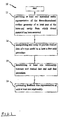
- Fig. 1 illustrates a method 10 for providing feedback data useful in at least one prosthodontic procedure associated with the intra oral cavity, in accordance with a first aspect of the invention.
- the method comprises the following basic steps:
- the feedback data is essentially used to facilitate the performance of a prosthodontic procedure with respect to the intraoral cavity.
- steps 11 to 14 are carried out in a relatively short space of time, more preferably in real time or close thereto.
- the first step 11 of the method according to the present invention relates to providing at least one numerical entity that is representative of the three-dimensional surface.
- the said numerical entity is typically at least "three-dimensional", that is, each data point of the data set comprises at least three prime independent variables relating to spatial coordinates of a surface, typically defined along orthogonal Cartesian axes, x, y, z. Alternatively, these variables may be defined along polar axes or any other geometric system in which a surface may be described.
- the numerical entity typically comprises a data set having a plurality of at least 3-dimensional arrays - (x, y, z), wherein each array represents the x, y, z, geometrical coordinates.
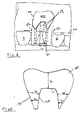
- Fig. 2 illustrates the main elements of the system 50 according to the present invention, comprising a suitable scanner 31 , a microprocessor or computer 52 , and a display means 54 .
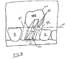
- digitised three-dimensional ( 3D ) information W (Fig. 3) of the patient's intra-oral cavity, or part thereof, is created by the system 50 using scanner 31 .
- the 3D digitized data of the intraoral cavity is obtained, including the dentition and associated anatomical structures of a patient.
- the scanning means 31 may include, for example, a handheld scanner that is used by the practitioner or other user to acquire the 3D data.
- a probe for determining three dimensional structure by confocal focusing of an array of light beams may be used, for example as manufactured under the name of PRUSTHOCAD or as disclosed in WO 00/08415 , the contents of which are incorporated herein in their entirety,
- the system 50 is typically located at a dental clinic, and may be linked to one or more service centers 23 and/or dental labs 26 , via a communication means or network such as for example the Internet or other suitable communications medium such as an intranet, local access network, public switched telephone network, cable network, satellite communication system, and the like, indicated by the cloud at 24 .
- a communication means or network such as for example the Internet or other suitable communications medium such as an intranet, local access network, public switched telephone network, cable network, satellite communication system, and the like, indicated by the cloud at 24 .
- such interlinked dental labs 26 may be further linked with other entities, for example a head clinic or head lab, comprising a centralized data base (not shown).
- the design and manufacture of dental appliances for use in the intraoral cavity may be eventually carried out at the dental lab 26 or at the service centre 23, or alternatively one or both of these activities may be shared between the two; in each case the design and manufacture are preferably based on the original 3D data of the oral cavity previously obtained.
- exchange of data between the system 50 and the dental lab 26 and/or service center 23 may be useful in creating an optimal geometry for a preparation being made in the intraoral cavity that enables the best prosthesis to be designed therefor, for example.
- the dental lab 26 typically comprises a laboratory, or a design or manufacturing entity that may provide direct technical services to the dental clinic in which the system 50 is located. Such services may include, for example, scanning, manufacturing, analyzing the preparation in the intra oral cavity to mark the location of the finish line, for example, as disclosed in USSN 10/623,707 and WO 04/008981, also assigned to the present assignee, and the contents of which are incorporated herein in their entirety, and so on.
- the dental lab 26 is typically characterized as being equipped or otherwise able to design part or whole prostheses, and/or to partially manufacture or assemble the same, particularly where close tolerances are relatively less critical.
- the service center 23 is also equipped to design part or whole prostheses, and/or to fully or partially manufacture and/or assemble the same, it is particularly suited to do any of these activities where close or tight tolerances are in fact critical and/or difficult to achieve.
- service centre 23 and dental labs 26 may be located in a different geographical zone to the dental clinic, for example, different countries, different cities in the same country, different neighborhoods in the same city, or even different buildings in the same neighborhood, they may also be housed in the same building, and in any case maintain their separate functions and capabilities, as described herein.
- the system 50 may also be linked to one or more consultation centers 27, also via network 24, wherein such consultation centers 27 may comprise dental experts, for example, that may provide feedback data to the user of system 50, based on data transmitted therefrom to the centers 27, according to the invention.
- consultation centers 27 may comprise dental experts, for example, that may provide feedback data to the user of system 50, based on data transmitted therefrom to the centers 27, according to the invention.
- step 11 is carried out after a material removal operation has been applied to a part of the intra oral cavity.
- a material removal operation may be executed using any suitable machining tool that is adapted for material removal, and may include inter alia mechanical tools such as drills for example, laser tools such as for example laser drills or cutters, ultrasonic tools such as for example ultrasonic cutters, and so on.
- the material removal operation may comprise a loss of dental material, occurring, for example, via disease, mechanical forces such as a blow to the teeth for example, and so on.
- Such a material removal operation may be directed for the purpose of, or may require, prosthodontic procedures, and may include the construction of a dental preparation at a dental site, so as to receive a prosthesis such as a crown, for example, or for providing a dental filling or restoration thereat.
- the 3D digitized data may be obtained in any other suitable manner, including other suitable intra oral scanning techniques, based on optical methods, direct contact or any other means, applied directly to the patient's dentition.
- suitable intra oral scanning techniques based on optical methods, direct contact or any other means, applied directly to the patient's dentition.
- X-ray based, CT based, MRI based, or any other type of scanning of the patient's intra-oral cavity may be used.
- the dimensional data may be associated with a complete dentition, or of a partial dentition, for example such as a preparation only of the intra oral cavity.
- the 3D digitized data is obtained in a manner such that enables the data to be procured from the patient and analysed according to the invention during a regular visit of a patient to a practitioner.
- such a scanner 31 makes use of confocal imaging for providing an accurate three-dimensional representation of the target surface within the intra-oral cavity.
- the numerical entity may further comprise a fourth prime independent variable, relating to a color parameter that is expressed numerically and is associated with the spatial coordinates.
- the color parameter may itself be comprised of independent prime color variables - for example relating to the red, blue and green (RGB) components associated with the color parameter.
- the color parameter may be expressed in terms of the Hue, Saturation and Intensity (HIS).
- HIS Hue, Saturation and Intensity
- any other color parameter may be used, including parameters that provide a measure of internal reflectance and translucency, or any other optical property of teeth.
- such a numerical entity typically comprises a data set having a plurality of 4-dimensional arrays - (x, y, z, c), wherein each array represents the x, y, z, geometrical coordinates, and wherein c represents the color value, of a point on a surface within the intra-oral cavity.
- Any suitable means may be used to provide this numerical entity.
- a three-dimensional surface scanner with color capabilities may be used.
- a scanner makes use of confocal imaging for providing an accurate three-dimensional representation of the target surface within the intra-oral cavity.
- Color values may then added to each data point of this data set by obtaining a two-dimensional color image of the target surface, and then mapping the color values of the two-dimensional image onto the three-dimensional "image", for example as described in co-pending applications assigned to the present assignee, USSN 60/580,109, entitled “METHOD FOR PROVIDING DATA ASSOCIATED WITH THE INTRAORAL CAVITY", and USSN 60/580,108, entitled “METHOD AND APPARATUS FOR COLOR IMAGING A THREE-DIMENSIONAL STRUCTURE”. These references are incorporated herein in their entirety by reference thereto.
- the procedure relates to the provision of a prosthesis, such as a crown or bridge, for example, and inlays, such as caps, for example, and any other artificial partial or complete denture.
- a prosthesis such as a crown or bridge
- inlays such as caps, for example, and any other artificial partial or complete denture.
- an area in the intra oral cavity needs to be prepared for receiving the crown, bridge and so on.
- crown prosthesis one tooth site needs to be prepared, while for a bridge prosthesis, two preparations need to be created, one at each of the abutment teeth for anchoring the bridge.
- Inlays require a different type of preparation at the tooth site.
- a virtual representation of such a crown generally designated 100, has an internal surface 120 and lower edge 130 that needs to be very precisely defined and manufactured to match the preparation 80 and finish line 84, respectively, in the intraoral cavity 200 of a patient. If the crown 100 is to comprise a coping 160 , the said internal surface 120 is that of the coping 160.
- the crown 100 which may be formed from a plurality of layers, preferably needs to have a natural looking appearance. Further, the dimensions of the crown 100, in particular the definition of the external surface 140 depends on external factors and needs to be such as to enable the crown 100 to fit between the adjacent teeth A, B, and to provide proper occlusion with the teeth D of the facing jaw (Fig. 3).
- the external surface 140 of the crown is such as to provide certain critical linear dimensions that comply with at least one of the target width or target height of a site or location on the jaw on which the crown is to be fitted.
- the target width may include the mesiodistal size of a tooth that is being replaced by the crown 100, and may be defined such as to provide adequate clearance between the crown 100 and adjacent teeth A, B, when the crown 100 is fixed onto the corresponding preparation in the intraoral cavity.
- the target height of the crown 100 may be defined such as to provide adequate occlusion with the "working side" of the tooth and avoiding interfering contact between the crown and teeth of the opposite jaw when the crown is fixed onto the corresponding preparation 80 in the intraoral cavity.
- An outer shape for the external surface 140 may be chosen in a number of ways. For example, if the original tooth that the crown 100 is replacing is still available, and the outer surface thereof is of a reasonable form, this original tooth may be scanned and the 3D data of the surface obtained. If necessary, this 3D data may be considered as a starting point, and the final shape of the external surface 140 is obtained by manipulating this data as required by the technician or other user that is designing the surface 140. Alternatively, if the patient has a reasonably healthy tooth on the same jaw but on the adjacent quadrant at a position corresponding to where the crown is to be fitted, the 3D data of the surface of this tooth is obtained.
- this tooth may be scanned as described herein to obtain the 3D spatial coordinates thereof, unless this data may already be available from the 3D data of the oral cavity 200 stored in the processor 52.
- 3D- data would need to be transformed to provide a lateral inversion of the coordinates, suitable for a prosthesis in the other half of the jaw.
- a suitable profile for surface 140 may be chosen and obtained from a library 35 that comprises the 3D spatial profiles of shapes or profiles of the outer surfaces of a plurality of crowns and teeth, If necessary the relative size and shape of the surface 140 may be adjusted by the user to better match the other teeth in the jaw.
- the chosen surface is adjusted in any suitable manner, either manually, automatically, interactively or in any other manner, in order that the required target dimensions of surface 140 will fit within a control volume that defines the maximum dimensions of the crown 100, as required to conform to the space available in the intra oral cavity 200.
- the control volume may be chosen such as to provide adequate clearance between the crown and adjacent teeth, and adequate occlusion with the opposite teeth, when the crown 100 is properly fixed onto the preparation.
- the processor 52 also has suitable software to define the inner surface 120 according to predetermined parameters. These parameters take into account the geometries of the external surface of the preparation 80 including finish line 84, the spacing required between the coping (if one is to be used with the crown) or the internal surface of the crown (if no coping is used) and the preparation to accommodate the adhesive or cement that is used to provide the bond between the two.
- the processor 52 may also comprise suitable software to provide the external shape of such a coping 160 , and thus provide a complete geometrical representation or 3D data of the coping 160, digitally.
- the external surface of the coping 160 may be defined in any number of ways.
- the thickness of the coping 160 may vary for a number of reasons. For example, it may be necessary in some cases to provide a coping that is stronger in some parts than in others, reflecting the activity that the crown 100 will be expected to engage in - as a molar, incisor, canine and so on.
- the design of the external surface 140 and the internal surface 120 may be executed by the processor 52 at the dental clinic, or alternatively at the service center 23, or at the dental lab 26. If at the latter, and if use is made of a library of 3D spatial profiles of shapes or profiles of the outer surfaces of a plurality of crowns and teeth, then the dental lab 26 can make use of library of the service centre 23, via communications network 24. Similarly, if the design is carried out at the dental clinic, the processor 52 may also make use of the library of the service centre 23, via communications network 24. Alternatively, the system 50 may have its own digital library 35 of 3D spatial profiles of shapes or profiles of the outer surfaces of a plurality of crowns and teeth, operatively connected to a processor 52 or other computer, as illustrated in Fig. 2, which comprises display 54 and user interface 59 such as a mouse and/or keyboard.
- the method 10 is adapted for providing feedback data regarding the definition of the finish line 84.
- it is desired to receive such feedback data referring to the quality and clearness of the finish line 84, and optionally including the shoulder 85.
- the finish line 84 may be of any type thereof, for example knife edge, feather edge, chamfer, chamfer bevel, shoulder, shoulder bevel, and so on.
- the finish line 84 may comprise a combination of different types around the periphery of the preparation, for example part of the finish line for a particular preparation may be knife edge, while another part may be feather edge.
- the processor 52 then manipulates the resulting numerical entity W to identify the finish line 84.
- This may be done using any suitable algorithm,
- the differentiation of dental surface color between the hard tissues and the soft tissues may be helpful in automatically defining the finish line, as described in the aforesaid co-pending application entitled "METHOD FOR PROVIDING DATA ASSOCIATED WITH THE INTRAORAL CAVITY".
- the shoulder type e.g., porcelain shoulder, metal collar and so on
- the geometry of the finish line 84 and optionally shoulder 85 may then be analysed by the processor 52 according to predetermined rules, to establish the relationship between the virtual finish line thus identified, and the function which the finish line 84 and optionally shoulder 85 is to play in the mounting of the prosthesis to the preparation.
- rules may comprise, for example one or more of the following:
- the processor 52 may then be established by the processor 52 whether the finish line 84 and/or shoulder 85 comply with such rules, and can then provide feedback data to the user.
- Such feedback data may take many different forms.
- the processor 52 may be adapted to transmit a signal via display 54.
- a signal may be an audio or visual signal, such as for example the sound of a bell 51 of a particular frequency or a colored light source 53 such as a green light, which may light up and remain lit, or may blink, or the signal may be more complex, such as for example a message on a screen stating that the finish line is suitable.
- the feedback data may first advise where the finish line is deficient. For example, if referring to the first rule listed above, there is a step or discontinuity along the periphery of the finish line, the location and extent of the same may be alerted to the user. For this purpose, a 3D representation of the preparation site may be displayed, with the part of the finish line in question highlighted in a different color to the rest of the finish line and/or of the preparation and so on.
- deviations in geometry from this type of finish line for example, part of the finish line is chamfered - may also be alerted to the user, for example by suitably annotating a graphical image of the preparation with colors and so on.
- the feed back data may also comprise indications to the user as to where to modify the finish line 84 or shoulder 85 to achieve better results.
- an image of the numerical entity may be displayed in the display 54, with the finish line 84 and optionally also the shoulder 85 highlighted thereon.
- the zones of the finish line that require further work may be contrasted with respect to the finish line 84 and/or the shoulder 85, for example by coloring such zones in a different color to the rest of the image.
- zones may be colored differently according to the type of work required. For example, zones deficient with respect to rule (a) above may be colored in red, while those deficient with respect to rule (b) are colored in blue, and so on.
- suggested changes to the finish line may be displayed on a two-dimensional representation of said dental preparation, via display 54, wherein said new finish line geometry may be superimposed over said representation.
- Modification of the finish line 84 and/or shoulder 85 typically requires a material removing operation, and after doing so, the intra oral cavity 200 may be re-scanned to provide a second numerical entity.
- the second numerical entity in particular the portions thereof relating to the finish line 84 or shoulder 85, may then be analysed as before to determine whether the finish line 84 or shoulder 85 are acceptable according to the predetermined rules, and without reference to the original entity W.
- the second numerical entity may be compared with the original entity W, and any deviations between the two entities may be highlighted in display 54 in order to facilitate the next cycle of modification to the finish line.
- the processor 52 may simply display the numerical entity and the highlighted finish line 84 and/or shoulder 85 on display 54, and this may at times represent sufficient feedback data for enabling the user to inspect the image thus created and to determine in a subjective manner whether the finish line and/or the shoulder are suitable or not.
- the processor 52 is suitably programmed to enable the numerical entities to be viewed at any suitable angle and /or magnification.
- the numerical entity W may be transmitted to one or more remote locations, such as for example a service center of dental lab 26, to be analysed there by a computer (not shown), or by a skilled technician or another user.
- the computer or skilled technician at the dental lab 26 may then communicate the results of the analysis to the original user via the communication network 24, or a different communication network, for example via cellular phone.
- These results may be in the form of numerical information that may be displayed, for example, or verbal instructions on how to proceed.
- the method 10 is adapted for providing feedback data regarding the suitability of the preparation to accept a prosthesis of a predetermined type.
- the method 10 according to this embodiment is adapted for providing feed back data regarding the type of prosthesis that may be suitable for use with the preparation 80.
- it is desired to receive such feedback data referring to at least one predetermined dimension, such as for example a characteristic thickness of a prosthesis with respect to the geometry of the preparation and the adjacent teeth A and B.
- the processor 52 then manipulates the resulting numerical entity W to identify the external surface 125 of the stump 82 of preparation 80 (Fig. 4). This may be done, for example, by first identifying the finish line and optionally shoulder, for example as described above, and then isolating the coping surface enclosed by the perimeter defined by the finish line and/or shoulder. Then, an external crown surface 140 is chosen or designed for the crown, such as to fit properly in the space between the adjacent teeth A, B, as described hereinbefore.
- the relationship between the external surface 125 (which is typically closely correlated to the internal surface 120 of the crown 100) or of the internal surface 120, and the external surface 140 may then be analysed by the processor 52 according to predetermined rules.
- This serves to establish the relationship between the thickness (referred to collectively herein as t) of the walls of crown 100, and the material from which the real crown (based on such a virtual crown 100) is to be produced as a function of the external surface 140 of the stump.
- t thickness of the walls of crown 100
- the material from which the real crown based on such a virtual crown 100
- such rules may comprise, for example one or more of the following:-
- the processor 52 may then be established by the processor 52 whether the geometry of the stump 82 complies with such rules, and can then provide suitable feedback data to the user.
- Such feedback data may take many different forms.
- the processor may be adapted to send a corresponding signal to display 54.
- a signal may be an audio or visual signal, such as for example the sound of a bell of a particular frequency or a colored light such as a green light, which may light up and remain lit, or may blink, or the signal may be more complex, such as a message on a screen stating that the finish line is suitable.
- a signal should be different from that provided with respect to the first embodiment described above, when both are available to the user.
- the feed back data may comprise indications to the user as follows:
- an image of the numerical entity W may be displayed in the display 54, with the stump highlighted thereon. Then, the zones of the stump that require further work may be contrasted with respect to the stump 82, for example by coloring such zones in a different color.
- zones may be colored differently according to the type of work required. For example, zones deficient with respect to rule (a) above may be colored in red, while those deficient with respect to rule (b) are colored in blue, and so on.
- the processor 52 provides a suitable signal to be displayed by display 54, and it may be necessary to replace the stump 84 with a pivot, core or past.
- a stump made from PFM Porcelaim Fused Metal
- a PFM crown was originally decided upon, it may be advisable to switch to a whole ceramic crown, and the processor 52 can determine whether the stump 82 would be suitable for such a crown.
- a contour or occlusion map of the target zone T may be provided, for example as disclosed in US 6,334,853 and EP 0984739, the contents of which are incorporated in their entirety herein, and which references are also assigned to the present assignee.
- a dental occlusion map is indicative of distances between opposite regions on facing surfaces of opposite dental surfaces of the upper jaws of the mouth, for example the preparation 80 and the opposed tooth D.
- the occlusion map may be created by manipulating the entity W so as to determine the distances between opposite regions on the opposite dental surfaces of the upper and lower jaws of the target zone T, and then setting up a correspondence between the determined distances and regions on a mapping surface.
- a colored contour map showing the occlusion distances with respect to the preparation 80 for example, and from this determine whether and what parts of the preparation require further work, or whether there is preparation adequacy or preparation clearance regarding the worked target zone T.
- the occlusion map may inform the practitioner whether the preparation is adequate for the type of crown that he/she was intending to use, or what type of crown may be used, if any, with the preparation in its present condition,
- a PFM crown typically requires greater occlusion between the preparation and opposed tooth (due the requirement for greater material thickness) than an all-ceramic crown, which in turn needs more clearance than a metal crown.
- the system 50 may be configured for automatically advising whether, for a given desired type of prosthesis (for example ceramic, PFM, metal and so on) the preparation is adequate, or conversely, given the current state of the preparation, what is the optimal type of prosthesis that is best suited for it, or if in fact the preparation is still unsuitable for receiving any prosthesis in its current state.
- a desired type of prosthesis for example ceramic, PFM, metal and so on
- the system 50 may be adapted to provide the practitioner with indications on how to further work the preparation so that it is optimally suited to the type of prosthesis that it is desired to be used therewith.
- the contour map and/or a graphical representation of the target zone T may be annotated, for example by suitably coloring corresponding areas therein, to indicate the corresponding areas of the preparation where more material needs to be removed, for example, fo as to accommodate a particular type of prosthesis.
- Modification of the stump 82 typically requires a material removing operation, and after doing so, the intra oral cavity may be re-scanned to provide a second numerical entity.
- the second numerical entity in particular the portions thereof relating to the stump 82, may then be analysed as before to determine whether the geometry of the stump 82 is acceptable according to the predetermined rules, and without reference to the original entity. Alternatively, such a second numerical entity may be compared with the original entity, and any deviations between the two may be highlighted in display 54 in order to facilitate the next cycle of modification to the stump 82.
- the processor 52 may simply display the numerical entity and the highlighted stump 82 on display 54, and this may at times represent sufficient feedback for enabling the user to inspect the image thus created and to determine in a subjective manner whether the stump 82 is suitable or not.
- the numerical entity may be transmitted to a remote location such as for example a dental lab 26, to be analysed there by a computer (not shown), or by a skilled technician or another user.
- the computer or skilled technician may then communicate the results of the analysis to the original user via the communication network 24 to provide feedback data to the original user regarding the stump 82 .
- the method 10 is adapted for providing the user with feed back data regarding the insertion path with respect to a preparation or preparations that is/are being created at a dental site for receiving a prosthesis such as a crown or bridge.
- the method 10 comprises the first step of providing a numerical entity of the intraoral cavity, including in particular the part of the cavity comprising the preparation.
- the numerical entity also comprises 3D data of the teeth A, B adjacent to the preparation 80.
- the 3D numerical entity may be provided in a similar manner to that described herein, mutatis mutandis.
- the processor 52 first identifies from the entity W the external surface 125 corresponding to the part of the preparation onto which the crown is to be mounted (Fig. 4), and suitable algorithms for this purpose may be created, possibly as described above for the second embodiment, mutatis mutandis" Then, a virtual model 100 of the crown is either created by the processor 52, or input thereto by the user or a third party such as service center or dental clinic 26, for example. Alternatively, this process may be commenced with a virtual model of the coping 160.
- the crown model 100 must be sized such as to fit between the adjacent teeth A, B, and thus be in abutting contact therewith when properly mounted onto the preparation 80 .
- the crown model 100 may be a full 3D model, comprising an external 3D surface, or may simply comprise key dimensional parameters, such as for example the mesiodistal width of the tooth between the adjacent teeth A, B.
- the crown model 100 also comprises a full 3D representation of the internal 3D surface 125, which may ge substantially complementary to the external surface 120 of the preparation, optionally taking into account an adhesive layer thickness that is to be introduced between the preparation and the said internal surface.
- the processor 52 then calculates the insertion path for the internal surface 120 of the virtual crown 100, and then checks whether this path is also suitable for the external surface 140 of the virtual crown 100. Alternatively, the processor 52 calculates the insertion path for the external surface 140 of the virtual crown 100, and then checks whether this path is also suitable for the internal surface 120 of the virtual crown 100. Ideally, the insertion path of the virtual crown 100 as a whole should enable the same to be maneuvered into position with respect to the preparation without colliding with or unduly interfering with other dental surfaces at or in the vicinity of the preparation.
- the geometry of the preparation 82 approximates a right frustro-conical cone, and the central axis 101 thereof is more or less perpendicular to the occlusal plane OP.
- the insertion path IP 1 of the internal surface constrains the external surface 140 to path IP 2 , which enables the external surface of the virtual crown 100 to be guided to the mounted position on the preparation without interfering or colliding with other parts of the dentition.
- the geometry of the preparation is approximately that of a slanting frustro-convex cone, wherein the central axis 101 thereof is at a minimum angle ⁇ to the occlusal plane.
- the insertion path IP 1 ' of the internal surface constrains the external surface to path IP 2 ', which would result in the external surface 140 of the virtual crown 100 colliding with adjacent tooth B, and it would be impossible to fit a real crown corresponding to the virtual crown 100 with such a preparation geometry.
- the insertion path IP 2 " of the external surface constrains the internal surface to path IP 1 ", which would result in an undercut part 105 of the virtual crown 100 colliding with the stump 82, and it would be impossible to fit a real crown corresponding to the virtual crown 100 with such a preparation geometry.
- the overhanging portion 88 and/or undercut part 105 may be highlighted by suitably coloring the corresponding zone in a graphical representation of the target zone T.
- another type of plan may be considered in place of or in conjunction with a material removal plan.
- Having a slanting frusto-conical profile for the preparation typically requires material to be removed until a substantial part of the overhanging portion 88 of the stump 82 is removed. Such a procedure may result in over-weakening of the stump 82.
- the overlapping areas of the stump 82 i.e., the part of the stump overshadowed by the overhanging portion 88 in the direction of the insertion path
- the overlapping areas or zones refer to portions of the crown 100 which would need to be removed to prevent collision of the internal surface 120 of the crown 100 with the stump 82. However, this would leave a substantial cavity between the part of the preparation and the corresponding part of the internal surface of the crown.
- This cavity is preferably filled by manufacturing an auxiliary prosthesis 121 having the shape of this cavity, and then bonding the auxiliary prosthesis to the stump 82, as illustrated in Fig. 9.
- suitable cement or filler material may be bonded to the overlapping areas, and these areas then subjected to a material removal operation to provide the desired result.
- the modified stump may be scanned to check the new geometry of the modified preparation.
- the insertion paths for prostheses are preferably substantially rectilinear, to ease the user's task in duplicating the path when maneuvering the real crown onto the preparation.
- the processor 52 can attempt to match such paths.
- the various alternatives may be presented to the user by means of display 54. Additionally or alternatively, the processor 52 may determine which matching pair is optimal, based on rules, or may present the different options in ascending or descending order of preference, according to any predetermined criteria, such as for example requiring a minimum number of direction or rotational changes in the path.
- display 54 displays an image of the dental site 200, together with the predicted insertion path of the internal surface and that of the external surface constrained thereby, or vice versa, and the processor 52 also provides the necessary input to the display 54 to highlight any part of the adjacent teeth A, B and/or preparation 80 that interfere with the particular insertion path.
- the processor 52 may generate a suitable warning signal, audio and/or visual, warning the user that the insertion path for the current preparation geometry is not suitable, and that remedial action is required.
- the processor may be programmed to determine possible plans for removing additional dental material from the preparation 80 to enable a suitable insertion path to be provided. This may be accomplished in a number of ways. For example, the processor may determine a particular suitable path for the external surface 140 of the virtual crown 100, for example the simplest and most direct path, and then identify the zones of the preparation which would need to be removed to prevent collision of the internal surface of the crown therewith, herein referred to as the "overlapping zones". However, since the internal surface of the crown is a function of the external geometry of the preparation, this procedure is preferably accomplished in a reiterative manner. That is, once the processor 52 identifies the overlapping zones, and removes, in a virtual manner, a small part of the overlapping zone.
- the amount of removal may be preset by the user, and any increment is possible. Preferably, such an amount may be correlated to the minimum removal of' material that is normally possible in an analogous real life situation.
- the processor 52 then adjusts the geometry of the internal surface of the virtual crown 100 to take into account the new preparation geometry, and examines the insertion path of the inner surface with respect to the new preparation geometry. If there is still interference between the internal surface and the preparation, more material is removed in the virtual sense, the geometry of the internal surface 120 adjusted, and the new internal surface insertion path re-examined for collision. Additional cycles may be performed until the external surface 125 of the preparation is suitably modified to be compatible with the insertion path.
- the result of such a virtual procedure may not be acceptable for a real crown, for example too much material needs to be removed, and this would provide a much weakened stump 82, according to pre-known rules.
- the virtual procedure may be repeated, each time starting with a different insertion path for the external surface 140, until a reasonable preparation geometry is arrived at that is compatible with the external insertion path and that is also reasonable according to such rules.
- the geometry of such a preparation is optionally, and preferably, analysed according to such rules, and a suitable warning provided to the user when the geometry of preparation is inherently unsuitable.
- the warning may be audio/and or visual, and may be simple, such as a bip or series of bips, or a flashing light or lights, or may be complex for example an audio or a visual message, created by the processor 52, actually describing the reason for the warning.
- a warning could comprise an audio and/or visual message stating "Warning! The stump geometry is defective!".
- the display 54 preferably comprises optional ear phone or headphones that enable the user to hear the message, but not the patient, since such a message may cause unnecessary alarm or anxiety to the patient.
- Such earphones or headphones may be operatively connected to the processor 52 via suitable cables, or via remote link such as an infrared transmitter/receiver system, or may be integrated into display 54, for example.
- a similar analysis and warning may be provided at the beginning of the exercise, and thus alert the user that the original preparation is unsuitable, preferably listing the reasons,
- the processor 52 may be programmed to provide recommendations, such as to remove the preparation completely, and to replace it with a pivot core or post.
- each plan comprises displaying the overlapping areas of the preparation that require to be modified, and the nature of the insertion path that is required for maneuvering the prosthesis into place. Both factors need to be weighed by the user before deciding how to proceed.
- the aforementioned overlapping areas can be displayed over an image of the dentition (provided from the 3D entity W), and preferably such an image can be manipulated, for example on a screen, to enable the user to fully study the plan.
- the user can modify the real preparation area in the intraoral cavity as closely as possible to the overlapping areas marked in the virtual model (3D numerical entity).
- the user may re-scan the intraoral cavity to check on the progress.
- the processor 52 may be further programmed to effectively overlay the new numerical entity over the original entity, in particular to highlight the differences in geometry between the areas in which actual material removal has occurred and the overlapping areas which were earmarked by the procedure for material removal. Further, the processor 52 may be further programmed to detect with respect to these entities where material still needs to be removed, and where too much material has been removed.
- the processor 52 recalculates the insertion path and advises the user whether the original modification plan is still possible, or whether the excess material removal requires a modification of the plan.
- a modification in the plan may be determined in a similar manner to the original plan, as described above, mutatis mutandis.
- the over modified areas have now rendered the preparation unsuitable according to the aforementioned rules, and the preparation must be replaced with an artificial pivot, core or post.
- the above method may also be adapted for the purpose of providing a suitable insertion path for the coping itself, mutatis mutandis.
- the methodology described above for the insertion path of a crown may be used, mutatis mutandis, for any dental restoration or dental prosthesis.
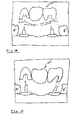
- preparations have to be created in the abutment teeth on either side of the missing tooth, and the geometries of both preparations need to be considered simultaneously in relation to the insertion path of the bridge as a unit.
- the preparation geometries illustrated allow the bridge 150 to be mounted via an insertion path 151, while the preparation geometries illustrated in Fig, 11 do not provide a common insertion path for the bridge 150 '.
- the processor 52 may provide one or more plans for the modification of one or both of the preparations, substantially as described above for a crown, mutatis mutandis, While the cases illustrated in Figs, 10 and 11 relate to a 3 -unit bridge, the aforegoing relates, mutatis mutandis, to a multiple unit bridge as well.
- the Fig. 12 illustrates a method 10' for providing feedback data useful in at least one prosthodontic procedure associated with the intra oral cavity, in accordance with a second aspect of the invention.
- the method is concerned with ensuring that numerical entity W sufficiently defines the area of interest of the intraoral cavity.
- the method 10' comprises the following basic steps:
- steps 11 ' to 14' are carried out in a relatively short space of time, more preferably in real time or close thereto.
- the first step 11' of the method according to the present invention relates to providing at least one numerical entity that is representative of the three-dimensional surface. This step is carried in a similar manner to step 11 of Fig. 1, as described above, mutatis mutandis,
- scanner 32 of system 50 (Fig. 2) scans the area of interest of the intraoral cavity and a numerical entity corresponding to the surface scanned is created by processor 52 and optionally displayed by display 54.
- the data from the scanner may be transmitted to a dental clinic 23, service centre 26, or consultancy centre 27, inter alia, for creation of the numerical entity, which is then transmitted to the processor 52.
- the processor 52 (or indeed another computer in the aforesaid dental clinic 23, service centre 26, or consultancy centre 27, inter alia) analyses the numerical entity to determine the sufficiency of definition of the numerical entity.
- the numerical entity may be obtained in a single scan, or alternatively, the numerical entity is originally created by taking multiple scans of the target area, and stitching the numerical entities thus obtained together.
- the processor 52 first checks whether the numerical entity lacks surface data in any particular part thereof Such a lack of data may be due to the user not passing the scanner over the full zone to be scanned, for example, or by taking multiple scan in wich there is insufficient overlap, for example..
- the scanner 31 may be used for obtaining high resolution numerical sub-entities representative of the surface topography within the intra-oral cavity. Accordingly, different zones of the intraoral cavity are sequentially scanned with scanner 31 to provide the corresponding sub entities. Some of these zones typically partially overlap with all the other zones, while other zones may only overlap with one or two other zones, and thus theoretically the corresponding sub-entities should have a portion of their data identical to one another within the overlap zone. However, since the scanner itself moves in orientation and position from scan to scan, the coordinates relating to these overlap zones will usually vary between adjacent scans, even though they relate to the same spatial feature.
- the spatial relationship between the entities may be established, and the various entities stitched together or combined to form a global numerical entity that comprises the full geometry and color representation of the target zone.
- the larger the overlap zone the greater the accuracy with which the different zones may be synchronized or stitched together spatially.
- the actual stitching technique may applied to data points corresponding to the hard tissues therein, which have a different color to the soft tissues such as gums, for example as described in the aforesaid co-pending application entitled "METHOD FOR PROVIDING DATA ASSOCIATED WITH THE INTRAORAL CAVITY".
- the zones that are scanned should preferably together fully span the target zone T of interest, however it sometimes happens that a part of the target zone is missed out, and thus after the stitching procedure is completed, the global numerical entity thus formed still lacks surface data in some areas.
- such areas are identified in steps 12' and 13' by the processor 52 which determines that the density of data points in some parts of the entity is below a predetermined value, indicative of a lack of data thereat, for example,
- the processor 52 can analyse the numerical entity in a different manner to determine whether it is sufficiently defined for this purpose. For example, having found quantitatively there is sufficient data, it is now necessary to determine if qualitatively the data is sufficient.
- the finish line may be well defined.
- parts of the finish line may be defined on a dental surface that is close to orthogonal with respect to the occlusal plane. If a confocal-type scanner is used at 31 for providing the surface data for this part of finish line, it is possible for the accuracy of definition of the finish line to be diminished the closer to parallel the output face of the scanner is with respect to the occlusal plane. Greater accuracy could be obtained in the scanner is turned to face the aforesaid dental surface close to face-on rather than close to edge-on.
- the processor 52 may determine whether the definition of the finish line is sufficiently good, and this may be done by comparing the orientation of the scanner 32 with respect to the aforesaid dental surface, according to preset criteria, for example. Thus, in step 13', the processor 52 determines whether data is missing, or whether the accuracy of the data of the numerical entity is insufficient
- step 14' feedback data is generated to alert the user as to how to correct for the insufficiency of definition.
- the processor 52 first identifies the missing areas for the user, and then may compute the best angle and position for the scanner 31 to scan the intraoral cavity such as to provide the missing surface data.
- This information may be provided by display 54, for example by providing a graphical image of the entity, with the deficient areas marked hereon, and then arrows or markers with respect thereto showing the desired position of the scanner 31.
- the processor provides the required feedback data to deal with each scan.
- the processor 52 may compute the best angle and position for the scanner 31 to scan the intraoral cavity such as to provide better definition of those areas.
- This information may also be provided by display 54, for example by providing a graphical image of the entity, and then arrows or markers with respect thereto showing the desired position of the scanner 31 .
- more than one scan may be required to provide the higher accuracy data, and the processor provides the required feedback data to deal with each scan.
- Other parts requiring special definition may include, for example, undercut zones of the preparation.
- the processor may be programmed to alert the user when the entity is sufficiently well defined for the purpose for which it is needed.
- the feedback data is deigned to alert the user that the scan is complete, and may comprise a distinct visual or audio signal, similar but distinguishable from other audio/visual signals provided by display 54, as described herein, mutatis mutandis.
- step 11 Fig. 1 of the first aspect of the invention, such as to ensure that the entity provided in step 11 is sufficient for steps 12 to 14 thereof
- the feedback data may essentially be used to facilitate the acquisition of data that may be used to construct the numerical entity for subsequent use, for example according to the first aspect of the invention.
- the entity obtained by scanning via scanner 31 is displayed in real time via display 54, and when the scanning is complete and acceptable, feedback data is provided alerting the user to this fact.
- the present invention may be used solely to obtain verification that a particular preparation is in a suitable condition for implanting a prosthesis.
- the analysis of the scanned data may also use the following parameters: the type of restoration required; patient parameters - age, sex, origin, dental condition (implants in the scanned area, root canals, soft tissue condition, and so on), budget for the procedure, and so on.
- the feedback data is essentially used in an interactive manner together with a material removing process to facilitate the performance of a procedure with respect to the intraoral cavity.
- the process for removing dental material to create the preparation may be effected in a number of stages, at the end of each material removing stage the preparation area being scanned and displayed in real time to guide the dental practitioner as to how to proceed to the next stage, such as to provide an optimal preparation geometry.
- the system guides the practitioner to provide the one of the preparation zones, and then based on this geometry calculates an optimal geometry for the second preparation zone required for the bridge, and correspondingly guides the practitioner accordingly.
- the processor 52 re-evaluates the full picture, and may suggest that the first preparation be modified instead of or in addition to the second preparation.
- At least the first aspect of the invention may be used with respect to a positive model of a dentition, in a similar manner to that described above for a real dentition, mutatis mutandis"
- the three dimensional entities in the oral cavity such as for example the teeth gums and so on, and also the 3D entities that are created by the system 50, including the preparation 10, for example, may be described instead by solid representations or any other topographical or geometrical representations.
- feedback data useful in prosthodontic procedures associated with the intra oral cavity is provided.
- a 3D numerical model of the target zone in the intra oral cavity is provided, and this is manipulated so as to extract particular data that may be useful in a particular procedure, for example data relating to the finish line or to the shape and size of a preparation.
- the relationship between this data and the procedure is then determined, for example the clearance between the preparation and the intended crown.
- Feedback data, indicative of this relationship is then generated, for example whether the preparation geometry is adequate for the particular type of prosthesis.
Applications Claiming Priority (1)
| Application Number | Priority Date | Filing Date | Title |
|---|---|---|---|
| US63057204P | 2004-11-26 | 2004-11-26 |
Publications (3)
| Publication Number | Publication Date |
|---|---|
| EP1662414A2 true EP1662414A2 (fr) | 2006-05-31 |
| EP1662414A3 EP1662414A3 (fr) | 2006-06-07 |
| EP1662414B1 EP1662414B1 (fr) | 2020-03-04 |
Family
ID=36088268
Family Applications (1)
| Application Number | Title | Priority Date | Filing Date |
|---|---|---|---|
| EP05111355.3A Active EP1662414B1 (fr) | 2004-11-26 | 2005-11-28 | Procédé et système de retour de données d' information utiles pour les procédures associées à la cavité intra-orale |
Country Status (2)
| Country | Link |
|---|---|
| US (8) | US7862336B2 (fr) |
| EP (1) | EP1662414B1 (fr) |
Cited By (9)
| Publication number | Priority date | Publication date | Assignee | Title |
|---|---|---|---|---|
| EP1738715A1 (fr) * | 2005-06-24 | 2007-01-03 | Implant & 3D Planungscenter GbR | Système et procédé d'évaluation d'une planification pour un implant |
| WO2007102729A1 (fr) * | 2006-03-08 | 2007-09-13 | Willem Boer | Procede de disposition d'un bridge sur un ensemble de dents et bridge pour l'application de ce procede |
| DE102006044215A1 (de) * | 2006-09-15 | 2008-03-27 | Sirona Dental Systems Gmbh | Verfahren zur Optimierung einer Einschubachsenrichtung eines als digitales 3D-Modell zu konstruierenden oder konstruierten Zahnersatzteils zu einem als 3D-Datensatz vorliegenden Präparationsgebiet |
| WO2009092613A2 (fr) * | 2008-01-25 | 2009-07-30 | Straumann Holding Ag | Procédé de modélisation d'une prothèse dentaire individuelle |
| WO2009094576A1 (fr) * | 2008-01-23 | 2009-07-30 | Sensable Technologies, Inc. | Système de modélisation dentaire activé de manière haptique |
| WO2015170162A1 (fr) * | 2014-05-07 | 2015-11-12 | Align Technology, Inc. | Identification de régions d'intérêt durant des balayages intra-buccaux |
| EP3182923B1 (fr) * | 2014-08-19 | 2020-04-22 | Align Technology, Inc. | Viseur avec suivi en temps réel pour balayage intrabuccal |
| KR102194777B1 (ko) * | 2020-06-10 | 2020-12-23 | 클리어테크놀로지 주식회사 | 인공지능 기반의 치과 보철 자동 디자인 설계 시스템 및 그 방법 |
| US20220015877A1 (en) * | 2012-05-03 | 2022-01-20 | 3Shape A/S | Designing an insertable dental restoration |
Families Citing this family (120)
| Publication number | Priority date | Publication date | Assignee | Title |
|---|---|---|---|---|
| US11026768B2 (en) | 1998-10-08 | 2021-06-08 | Align Technology, Inc. | Dental appliance reinforcement |
| DE10041003A1 (de) * | 2000-08-22 | 2002-03-28 | Sueddeutsche Kalkstickstoff | Verfahren zum Imprägnieren einer Trägermatrix mit festen und/oder flüssigen Verbindungen mit Hilfe komprimierter Gase und so imprägnierte Stoffe |
| US6915178B2 (en) | 2000-09-06 | 2005-07-05 | O'brien Dental Lab, Inc. | Dental prosthesis manufacturing process, dental prosthesis pattern & dental prosthesis made thereby |
| US20040166462A1 (en) | 2003-02-26 | 2004-08-26 | Align Technology, Inc. | Systems and methods for fabricating a dental template |
| US7333874B2 (en) | 2004-02-24 | 2008-02-19 | Cadent Ltd. | Method and system for designing and producing dental prostheses and appliances |
| US9492245B2 (en) | 2004-02-27 | 2016-11-15 | Align Technology, Inc. | Method and system for providing dynamic orthodontic assessment and treatment profiles |
| US7862336B2 (en) | 2004-11-26 | 2011-01-04 | Cadent Ltd. | Method and system for providing feedback data useful in prosthodontic procedures associated with the intra oral cavity |
| US7819662B2 (en) * | 2004-11-30 | 2010-10-26 | Geodigm Corporation | Multi-component dental appliances and a method for constructing the same |
| US7555403B2 (en) | 2005-07-15 | 2009-06-30 | Cadent Ltd. | Method for manipulating a dental virtual model, method for creating physical entities based on a dental virtual model thus manipulated, and dental models thus created |
| CA2618065C (fr) * | 2005-08-10 | 2014-06-10 | Dentsply International Inc. | Procedes de preparation de couronnes dentaires a realiser sur le patient |
| DE102006033794B3 (de) * | 2006-07-19 | 2008-03-06 | BEGO Bremer Goldschlägerei Wilh. Herbst GmbH & Co. KG | Elementesatz zur Herstellung einer dentalen Prothese, System zur Herstellung einer dentalen Prothese oder eines Elementesatzes sowie entsprechende Herstellverfahren |
| EP2117750A2 (fr) * | 2006-11-07 | 2009-11-18 | Geodigm Corporation | Dispositifs de formage de descente de coulée |
| US20090148816A1 (en) * | 2007-01-11 | 2009-06-11 | Geodigm Corporation | Design of dental appliances |
| WO2008086526A2 (fr) * | 2007-01-11 | 2008-07-17 | Geodigm Corporation | Conception d'appareils dentaires |
| US7878805B2 (en) | 2007-05-25 | 2011-02-01 | Align Technology, Inc. | Tabbed dental appliance |
| DE102007034653A1 (de) * | 2007-07-25 | 2009-01-29 | Aepsilon Rechteverwaltungs Gmbh | Verfahren zum Entwerfen eines Zahnersatzteils, Verfahren zum Bearbeiten eines entworfenen Zahnersatzteils, Zahnersatzteil und computerlesbares Medium |
| JP5638392B2 (ja) * | 2007-09-26 | 2014-12-10 | ディーフォーディー テクノロジーズ エルエルシー | インプラント支台歯のための歯冠の製造方法 |
| EP3533411B1 (fr) | 2007-10-12 | 2022-03-16 | Align Technology, Inc. | Appareil prosthodontique et orthodontique et procédés |
| US8100692B2 (en) * | 2007-10-19 | 2012-01-24 | Cagenix Incorporated | Dental framework |
| US8738394B2 (en) | 2007-11-08 | 2014-05-27 | Eric E. Kuo | Clinical data file |
| US8108189B2 (en) | 2008-03-25 | 2012-01-31 | Align Technologies, Inc. | Reconstruction of non-visible part of tooth |
| US8092215B2 (en) | 2008-05-23 | 2012-01-10 | Align Technology, Inc. | Smile designer |
| US9492243B2 (en) | 2008-05-23 | 2016-11-15 | Align Technology, Inc. | Dental implant positioning |
| US8172569B2 (en) | 2008-06-12 | 2012-05-08 | Align Technology, Inc. | Dental appliance |
| US8509932B2 (en) | 2008-07-17 | 2013-08-13 | Cadent Ltd. | Methods, systems and accessories useful for procedures relating to dental implants |
| US20100035212A1 (en) * | 2008-08-11 | 2010-02-11 | Jean Robichaud | Preparation of dental implant surgery and prosthesis installation |
| US8152518B2 (en) | 2008-10-08 | 2012-04-10 | Align Technology, Inc. | Dental positioning appliance having metallic portion |
| US20100192375A1 (en) | 2009-02-02 | 2010-08-05 | Remedent Nv | Method for producing a dentist tool |
| US8640338B2 (en) | 2009-02-02 | 2014-02-04 | Viax Dental Technologies, LLC | Method of preparation for restoring tooth structure |
| US8292617B2 (en) | 2009-03-19 | 2012-10-23 | Align Technology, Inc. | Dental wire attachment |
| US8867800B2 (en) * | 2009-05-27 | 2014-10-21 | James R. Glidewell Dental Ceramics, Inc. | Method of designing and fabricating patient-specific restorations from intra-oral scanning of a digital impression |
| US8765031B2 (en) | 2009-08-13 | 2014-07-01 | Align Technology, Inc. | Method of forming a dental appliance |
| US8457772B2 (en) * | 2010-02-10 | 2013-06-04 | Biocad Medical, Inc. | Method for planning a dental component |
| US9934360B2 (en) * | 2010-02-10 | 2018-04-03 | Biocad Medical, Inc. | Dental data planning |
| WO2011102118A1 (fr) * | 2010-02-16 | 2011-08-25 | 財団法人ヒューマンサイエンス振興財団 | Procédé de fabrication d'un élément de revêtement dentaire et appareil de conception assistée par ordinateur (cad)/fabrication assistée par ordinateur (cam) dentaire |
| US9241774B2 (en) | 2010-04-30 | 2016-01-26 | Align Technology, Inc. | Patterned dental positioning appliance |
| US9211166B2 (en) | 2010-04-30 | 2015-12-15 | Align Technology, Inc. | Individualized orthodontic treatment index |
| US9179988B2 (en) | 2010-05-25 | 2015-11-10 | Biocad Medical, Inc. | Dental prosthesis connector design |
| EP2593035B1 (fr) | 2010-07-12 | 2019-12-11 | 3Shape A/S | Modélisation 3d d'un objet en utilisant des éléments texturaux |
| ES2848157T3 (es) | 2010-07-19 | 2021-08-05 | Align Technology Inc | Procedimientos y sistemas para crear e interactuar con modelos virtuales tridimensionales |
| US9089387B2 (en) * | 2010-07-23 | 2015-07-28 | Biocad Medical, Inc. | Surface manipulation in dental prosthesis design |
| US8712733B2 (en) * | 2010-09-17 | 2014-04-29 | Biocad Medical, Inc. | Adjusting dental prostheses based on soft tissue |
| MX2013013872A (es) | 2011-05-26 | 2014-05-28 | Viax Dental Technologies Llc | Herramienta dental y dispositivos de guia. |
| US9504533B2 (en) * | 2011-09-16 | 2016-11-29 | Ibur, Llc | Edentulous surgical guide |
| US9403238B2 (en) | 2011-09-21 | 2016-08-02 | Align Technology, Inc. | Laser cutting |
| US9375300B2 (en) | 2012-02-02 | 2016-06-28 | Align Technology, Inc. | Identifying forces on a tooth |
| US9220580B2 (en) | 2012-03-01 | 2015-12-29 | Align Technology, Inc. | Determining a dental treatment difficulty |
| US9414897B2 (en) | 2012-05-22 | 2016-08-16 | Align Technology, Inc. | Adjustment of tooth position in a virtual dental model |
| DE102012214473B4 (de) * | 2012-08-14 | 2022-01-13 | Sirona Dental Systems Gmbh | Verfahren zur Vermessung eines dentalen Objekts mittels einer dentalen Kamera |
| JP6640088B2 (ja) * | 2013-08-26 | 2020-02-05 | ジェームズ アール. グライドウェル デンタル セラミックス,インコーポレーテッド | コンピュータにより実行される歯科修復物設計 |
| DE102014201993A1 (de) * | 2014-02-04 | 2015-08-06 | Sirona Dental Systems Gmbh | Verfahren zur computergestützten Bearbeitung eines digitalen 3D-Modells |
| US10426711B2 (en) | 2014-05-08 | 2019-10-01 | Cagenix, Inc. | Dental implant framework |
| US10980618B2 (en) | 2014-05-08 | 2021-04-20 | Cagenix, Inc. | Dental framework and prosthesis |
| US10772506B2 (en) | 2014-07-07 | 2020-09-15 | Align Technology, Inc. | Apparatus for dental confocal imaging |
| US9675430B2 (en) | 2014-08-15 | 2017-06-13 | Align Technology, Inc. | Confocal imaging apparatus with curved focal surface |
| US9610141B2 (en) | 2014-09-19 | 2017-04-04 | Align Technology, Inc. | Arch expanding appliance |
| US10449016B2 (en) | 2014-09-19 | 2019-10-22 | Align Technology, Inc. | Arch adjustment appliance |
| US9744001B2 (en) | 2014-11-13 | 2017-08-29 | Align Technology, Inc. | Dental appliance with cavity for an unerupted or erupting tooth |
| US10504386B2 (en) | 2015-01-27 | 2019-12-10 | Align Technology, Inc. | Training method and system for oral-cavity-imaging-and-modeling equipment |
| US9770217B2 (en) * | 2015-01-30 | 2017-09-26 | Dental Imaging Technologies Corporation | Dental variation tracking and prediction |
| US10248883B2 (en) | 2015-08-20 | 2019-04-02 | Align Technology, Inc. | Photograph-based assessment of dental treatments and procedures |
| US11931222B2 (en) | 2015-11-12 | 2024-03-19 | Align Technology, Inc. | Dental attachment formation structures |
| US11554000B2 (en) | 2015-11-12 | 2023-01-17 | Align Technology, Inc. | Dental attachment formation structure |
| US11103330B2 (en) | 2015-12-09 | 2021-08-31 | Align Technology, Inc. | Dental attachment placement structure |
| US11596502B2 (en) | 2015-12-09 | 2023-03-07 | Align Technology, Inc. | Dental attachment placement structure |
| US20180368956A1 (en) * | 2015-12-21 | 2018-12-27 | 3Shape A/S | Method for designing a restoration and a reduction coping |
| WO2017218947A1 (fr) | 2016-06-17 | 2017-12-21 | Align Technology, Inc. | Appareils intraoraux avec détection |
| US10383705B2 (en) | 2016-06-17 | 2019-08-20 | Align Technology, Inc. | Orthodontic appliance performance monitor |
| US10136972B2 (en) * | 2016-06-30 | 2018-11-27 | Align Technology, Inc. | Historical scan reference for intraoral scans |
| GB2552137A (en) | 2016-07-03 | 2018-01-17 | Tarazi Eyal | Systems and methods of automated control of in-situ preparation for prefabricated fixed dental prosthesis |
| US10507087B2 (en) | 2016-07-27 | 2019-12-17 | Align Technology, Inc. | Methods and apparatuses for forming a three-dimensional volumetric model of a subject's teeth |
| DK3578131T3 (da) | 2016-07-27 | 2020-12-21 | Align Technology Inc | Intraoral scanner med dentale diagnosticeringsegenskaber |
| WO2018085718A2 (fr) | 2016-11-04 | 2018-05-11 | Align Technology, Inc. | Procédés et appareils de prise d'images dentaires |
| WO2018102770A1 (fr) | 2016-12-02 | 2018-06-07 | Align Technology, Inc. | Commande de force, mécanisme d'arrêt, structure de régulation d'appareil de réglage d'arcade amovible |
| WO2018102702A1 (fr) | 2016-12-02 | 2018-06-07 | Align Technology, Inc. | Caractéristiques d'un appareil dentaire permettant l'amélioration de la parole |
| AU2017366755B2 (en) | 2016-12-02 | 2022-07-28 | Align Technology, Inc. | Methods and apparatuses for customizing rapid palatal expanders using digital models |
| CN110035708B (zh) | 2016-12-02 | 2021-11-05 | 阿莱恩技术有限公司 | 腭扩张器和扩张腭的方法 |
| US10888399B2 (en) | 2016-12-16 | 2021-01-12 | Align Technology, Inc. | Augmented reality enhancements for dental practitioners |
| US10548700B2 (en) | 2016-12-16 | 2020-02-04 | Align Technology, Inc. | Dental appliance etch template |
| US10467815B2 (en) | 2016-12-16 | 2019-11-05 | Align Technology, Inc. | Augmented reality planning and viewing of dental treatment outcomes |
| US10456043B2 (en) | 2017-01-12 | 2019-10-29 | Align Technology, Inc. | Compact confocal dental scanning apparatus |
| US10779718B2 (en) | 2017-02-13 | 2020-09-22 | Align Technology, Inc. | Cheek retractor and mobile device holder |
| IT201700017965A1 (it) | 2017-02-17 | 2018-08-17 | Silvio Franco Emanuelli | Metodo e sistema di simulazione di sito implantare ottimizzato |
| EP3582717B1 (fr) * | 2017-02-17 | 2023-08-09 | Silvio Franco Emanuelli | Système et procédé de surveillance d'implants dentaires optimaux pouvant être accouplés à un site d'implantation optimisé |
| US10499793B2 (en) | 2017-02-17 | 2019-12-10 | Align Technology, Inc. | Longitudinal analysis and visualization under limited accuracy system |
| US11007035B2 (en) | 2017-03-16 | 2021-05-18 | Viax Dental Technologies Llc | System for preparing teeth for the placement of veneers |
| US10613515B2 (en) | 2017-03-31 | 2020-04-07 | Align Technology, Inc. | Orthodontic appliances including at least partially un-erupted teeth and method of forming them |
| US11045283B2 (en) | 2017-06-09 | 2021-06-29 | Align Technology, Inc. | Palatal expander with skeletal anchorage devices |
| WO2019005808A1 (fr) | 2017-06-26 | 2019-01-03 | Align Technology, Inc. | Indicateur de performance de biocapteur pour appareils intrabuccaux |
| US10885521B2 (en) | 2017-07-17 | 2021-01-05 | Align Technology, Inc. | Method and apparatuses for interactive ordering of dental aligners |
| CN111107806B (zh) | 2017-07-21 | 2022-04-19 | 阿莱恩技术有限公司 | 颚轮廓锚固 |
| EP4278957A3 (fr) | 2017-07-27 | 2024-01-24 | Align Technology, Inc. | Système et procédés de traitement d'un aligneur orthodontique au moyen d'une tomographie par cohérence optique |
| WO2019023461A1 (fr) | 2017-07-27 | 2019-01-31 | Align Technology, Inc. | Teinte, transparence et émaillage dentaire |
| WO2019035979A1 (fr) | 2017-08-15 | 2019-02-21 | Align Technology, Inc. | Évaluation et calcul de couloir buccal |
| WO2019036677A1 (fr) | 2017-08-17 | 2019-02-21 | Align Technology, Inc. | Surveillance de conformité d'appareil dentaire |
| US10813720B2 (en) | 2017-10-05 | 2020-10-27 | Align Technology, Inc. | Interproximal reduction templates |
| DE102017124580B3 (de) * | 2017-10-20 | 2019-01-31 | Sicat Gmbh & Co. Kg | Verfahren zur Ermittlung und Visualisierung von Zahnstellungen unter Einwirkung von Beißkräften |
| EP3700458B1 (fr) | 2017-10-27 | 2023-06-07 | Align Technology, Inc. | Autres structures de réglage de morsure |
| JP7051371B2 (ja) * | 2017-10-31 | 2022-04-11 | 株式会社松風 | スキャンによって変化した支台歯形態を推定復元する方法及びそのプログラム |
| CN111295153B (zh) | 2017-10-31 | 2023-06-16 | 阿莱恩技术有限公司 | 具有选择性牙合负荷和受控牙尖交错的牙科器具 |
| EP3703607A2 (fr) | 2017-11-01 | 2020-09-09 | Align Technology, Inc. | Planification automatique de traitement |
| WO2019100022A1 (fr) | 2017-11-17 | 2019-05-23 | Align Technology, Inc. | Dispositifs de retenue orthodontiques |
| EP3716885B1 (fr) | 2017-11-30 | 2023-08-30 | Align Technology, Inc. | Appareils buccaux orthodontiques comprenant des capteurs |
| WO2019118876A1 (fr) | 2017-12-15 | 2019-06-20 | Align Technology, Inc. | Méthodes et appareils de traitement orthodontique adaptatif à boucle fermée |
| US10980613B2 (en) | 2017-12-29 | 2021-04-20 | Align Technology, Inc. | Augmented reality enhancements for dental practitioners |
| US10952816B2 (en) | 2018-01-26 | 2021-03-23 | Align Technology, Inc. | Visual prosthetic and orthodontic treatment planning |
| AU2019212649A1 (en) | 2018-01-26 | 2020-07-02 | Align Technology, Inc. | Diagnostic intraoral scanning and tracking |
| US11937991B2 (en) | 2018-03-27 | 2024-03-26 | Align Technology, Inc. | Dental attachment placement structure |
| CN116211501A (zh) | 2018-04-11 | 2023-06-06 | 阿莱恩技术有限公司 | 腭扩张器、腭扩张器设备及系统、腭扩张器的形成方法 |
| US20210386529A1 (en) * | 2018-11-07 | 2021-12-16 | Implant Solutions Pty Ltd | A dental prosthesis |
| US20200155274A1 (en) * | 2018-11-16 | 2020-05-21 | Align Technology, Inc. | Dental analysis with missing teeth prediction |
| US11364101B2 (en) | 2018-12-03 | 2022-06-21 | Cagenix, Inc. | Dental implant framework |
| JP7016328B2 (ja) * | 2019-02-02 | 2022-02-04 | 株式会社医科歯科ソリューションズ | 歯冠補綴物のエッジ部の修正方法 |
| KR102138920B1 (ko) * | 2019-04-25 | 2020-07-28 | 오스템임플란트 주식회사 | 보철물 설계 시 언더컷 영역 표시방법 및 이를 수행하는 보철 캐드 장치 |
| US11351015B2 (en) | 2019-07-01 | 2022-06-07 | James R. Glidewell Dental Ceramics, Inc. | Reduction or guidance coping |
| US20210059796A1 (en) * | 2019-09-04 | 2021-03-04 | Align Technology, Inc. | Automated detection, generation and/or correction of dental features in digital models |
| JP6868255B2 (ja) * | 2019-10-29 | 2021-05-12 | 株式会社ワイドソフトデザイン | 支台歯形成支援装置 |
| US11538573B2 (en) | 2020-03-30 | 2022-12-27 | James R. Glidewell Dental Ceramics, Inc. | Virtual dental restoration insertion verification |
| EP4322886A1 (fr) * | 2021-04-12 | 2024-02-21 | 3M Innovative Properties Company | Processus de gestion de couleur pour des restaurations dentaires personnalisées |
| WO2023059167A1 (fr) * | 2021-10-08 | 2023-04-13 | 주식회사 메디트 | Dispositif de traitement d'image buccale et procédé de traitement d'image buccale |
Citations (3)
| Publication number | Priority date | Publication date | Assignee | Title |
|---|---|---|---|---|
| WO2000008415A1 (fr) | 1998-08-05 | 2000-02-17 | Cadent Ltd. | Imagerie d'une structure tridimensionnelle par focalisation confocale d'un reseau de faisceaux lumineux |
| EP0984739A1 (fr) | 1997-05-22 | 2000-03-15 | Cadent Ltd. | Procede d'obtension d'une carte des occlusions dentaires |
| WO2004008981A2 (fr) | 2002-07-22 | 2004-01-29 | Cadent Ltd. | Procede pour definir une ligne de finition d'une prothese dentaire |
Family Cites Families (198)
| Publication number | Priority date | Publication date | Assignee | Title |
|---|---|---|---|---|
| US1032787A (en) | 1911-07-08 | 1912-07-16 | Harold Douglas Singer | Steam-trap. |
| US2467432A (en) | 1943-07-23 | 1949-04-19 | Harold D Kesling | Method of making orthodontic appliances and of positioning teeth |
| US3407500A (en) | 1966-05-06 | 1968-10-29 | Peter C. Kesling | Tooth positioner |
| US3660900A (en) | 1969-11-10 | 1972-05-09 | Lawrence F Andrews | Method and apparatus for improved orthodontic bracket and arch wire technique |
| US3600808A (en) | 1970-01-22 | 1971-08-24 | James Jackson Reeve | Anterior root-torquing auxiliary wire |
| US3860803A (en) | 1970-08-24 | 1975-01-14 | Diecomp Inc | Automatic method and apparatus for fabricating progressive dies |
| US3683502A (en) | 1970-09-14 | 1972-08-15 | Melvin Wallshein | Orthodontic systems |
| US3738005A (en) | 1972-03-22 | 1973-06-12 | M Cohen | Method and apparatus for applying orthodontic brackets and the like |
| US3916526A (en) | 1973-05-10 | 1975-11-04 | Fred Frank Schudy | Method and apparatus for orthodontic treatment |
| US3922786A (en) | 1974-01-30 | 1975-12-02 | Joseph L Lavin | Method and apparatus for forming and fitting orthodontic appliances |
| US3983628A (en) | 1975-01-24 | 1976-10-05 | Raul Acevedo | Dental articulator, new bite registration guide, and diagnostic procedure associated with stereodont orthodontic study model |
| US3950851A (en) | 1975-03-05 | 1976-04-20 | Bergersen Earl Olaf | Orthodontic positioner and method for improving retention of tooth alignment therewith |
| US4014096A (en) | 1975-03-25 | 1977-03-29 | Dellinger Eugene L | Method and apparatus for orthodontic treatment |
| JPS5358191A (en) | 1976-11-05 | 1978-05-25 | Osamu Yoshii | Method of producing dental correction treating instrument using silicon resin material |
| US4348178A (en) | 1977-01-03 | 1982-09-07 | Kurz Craven H | Vibrational orthodontic appliance |
| US4195046A (en) | 1978-05-04 | 1980-03-25 | Kesling Peter C | Method for molding air holes into a tooth positioning and retaining appliance |
| US4324547A (en) | 1978-09-16 | 1982-04-13 | Vishay Intertechnology, Inc. | Dentistry technique |
| US4253828A (en) | 1979-04-09 | 1981-03-03 | Coles Donna C | Orthodontic appliance |
| DE2936847A1 (de) | 1979-09-12 | 1981-03-19 | Paul Dr. 6054 Rodgau Heitlinger | Verfahren zur herstellung von zahnersatz und vorrichtung zur durchfuehrung des verfahrens |
| US4575805A (en) | 1980-12-24 | 1986-03-11 | Moermann Werner H | Method and apparatus for the fabrication of custom-shaped implants |
| DE3203937C2 (de) | 1982-02-05 | 1985-10-03 | Luc Dr. 4150 Krefeld Barrut | Verfahren und Vorrichtung zum maschinellen Sanieren oder Korrigieren mindestens eines Zahnes oder zum maschinellen Vorbereiten mindestens eines Zahnes für eine festsitzende prothetische Restaurierung und zum maschinellen Herstellen der festsitzenden prothetischen Restaurierung |
| FR2525103B1 (fr) * | 1982-04-14 | 1985-09-27 | Duret Francois | Dispositif de prise d'empreinte par des moyens optiques, notamment en vue de la realisation automatique de protheses |
| FR2536654B1 (fr) * | 1982-11-30 | 1987-01-09 | Duret Francois | Procede de realisation d'une prothese dentaire |
| US4663720A (en) | 1984-02-21 | 1987-05-05 | Francois Duret | Method of and apparatus for making a prosthesis, especially a dental prosthesis |
| US4500294A (en) | 1983-10-03 | 1985-02-19 | Epic International Corporation | Method and device for detecting dental cavities |
| US4526540A (en) | 1983-12-19 | 1985-07-02 | Dellinger Eugene L | Orthodontic apparatus and method for treating malocclusion |
| DE3415006A1 (de) | 1984-04-19 | 1985-11-07 | Helge Dr. 8000 München Fischer-Brandies | Zahntechnisches verfahren und vorrichtung zum biegen und tordieren eines drahtstueckes |
| US4798534A (en) | 1984-08-03 | 1989-01-17 | Great Lakes Orthodontic Laboratories Inc. | Method of making a dental appliance |
| US4575330A (en) | 1984-08-08 | 1986-03-11 | Uvp, Inc. | Apparatus for production of three-dimensional objects by stereolithography |
| US4609349A (en) | 1984-09-24 | 1986-09-02 | Cain Steve B | Active removable orthodontic appliance and method of straightening teeth |
| US4591341A (en) | 1984-10-03 | 1986-05-27 | Andrews Lawrence F | Orthodontic positioner and method of manufacturing same |
| US4664626A (en) | 1985-03-19 | 1987-05-12 | Kesling Peter C | System for automatically preventing overtipping and/or overuprighting in the begg technique |
| US4763791A (en) | 1985-06-06 | 1988-08-16 | Excel Dental Studios, Inc. | Dental impression supply kit |
| GB2176402B (en) | 1985-06-20 | 1989-04-19 | Craig Med Prod Ltd | Wound management appliance for use on the human skin |
| US4936862A (en) | 1986-05-30 | 1990-06-26 | Walker Peter S | Method of designing and manufacturing a human joint prosthesis |
| CH672722A5 (fr) | 1986-06-24 | 1989-12-29 | Marco Brandestini | |
| CA1284040C (fr) | 1986-06-26 | 1991-05-14 | Peter C. Kesling | Bracket "edgewise" permettant la bascule de la couronne libre et un degre predetermine de redressement de la racine |
| US4877398A (en) | 1987-04-16 | 1989-10-31 | Tp Orthodontics, Inc. | Bracket for permitting tipping and limiting uprighting |
| US4676747A (en) | 1986-08-06 | 1987-06-30 | Tp Orthodontics, Inc. | Torquing auxiliary |
| US4983334A (en) | 1986-08-28 | 1991-01-08 | Loren S. Adell | Method of making an orthodontic appliance |
| US4755139A (en) | 1987-01-29 | 1988-07-05 | Great Lakes Orthodontics, Ltd. | Orthodontic anchor appliance and method for teeth positioning and method of constructing the appliance |
| US4850864A (en) | 1987-03-30 | 1989-07-25 | Diamond Michael K | Bracket placing instrument |
| US4850865A (en) | 1987-04-30 | 1989-07-25 | Napolitano John R | Orthodontic method and apparatus |
| US5186623A (en) | 1987-05-05 | 1993-02-16 | Great Lakes Orthodontics, Ltd. | Orthodontic finishing positioner and method of construction |
| US4856991A (en) | 1987-05-05 | 1989-08-15 | Great Lakes Orthodontics, Ltd. | Orthodontic finishing positioner and method of construction |
| US4836778A (en) | 1987-05-26 | 1989-06-06 | Vexcel Corporation | Mandibular motion monitoring system |
| DE3723555C2 (de) | 1987-07-16 | 1994-08-11 | Steinbichler Hans | Verfahren zur Herstellung von Zahnersatz |
| NL8702391A (nl) | 1987-10-07 | 1989-05-01 | Elephant Edelmetaal Bv | Werkwijze voor het met behulp van een cad-cam systeem vervaardigen van een dentaalkroon voor een gebitspreparatie. |
| US4793803A (en) | 1987-10-08 | 1988-12-27 | Martz Martin G | Removable tooth positioning appliance and method |
| US4880380A (en) | 1987-10-13 | 1989-11-14 | Martz Martin G | Orthodonture appliance which may be manually installed and removed by the patient |
| US5130064A (en) | 1988-04-18 | 1992-07-14 | 3D Systems, Inc. | Method of making a three dimensional object by stereolithography |
| US4941826A (en) | 1988-06-09 | 1990-07-17 | William Loran | Apparatus for indirect dental machining |
| JPH0766445B2 (ja) * | 1988-09-09 | 1995-07-19 | 工業技術院長 | 画像処理方法 |
| US5100316A (en) | 1988-09-26 | 1992-03-31 | Wildman Alexander J | Orthodontic archwire shaping method |
| US5055039A (en) | 1988-10-06 | 1991-10-08 | Great Lakes Orthodontics, Ltd. | Orthodontic positioner and methods of making and using same |
| FR2639211A1 (fr) * | 1988-11-18 | 1990-05-25 | Hennson Int | Procede de correlation des saisies tridimensionnelles d'organes humains et dispositif pour sa mise en oeuvre |
| US4935635A (en) | 1988-12-09 | 1990-06-19 | Harra Dale G O | System for measuring objects in three dimensions |
| IL88842A (en) * | 1988-12-30 | 1990-07-26 | Shafir Aaron | Apparatus and method for digitizing the contour of a surface particularly useful for preparing a dental crown |
| US5011405A (en) | 1989-01-24 | 1991-04-30 | Dolphin Imaging Systems | Method for determining orthodontic bracket placement |
| WO1990008505A1 (fr) | 1989-01-24 | 1990-08-09 | Dolphin Imaging Systems Inc. | Procede et appareil de generation d'images cephalometriques |
| US4889238A (en) | 1989-04-03 | 1989-12-26 | The Procter & Gamble Company | Medicament package for increasing compliance with complex therapeutic regimens |
| US4975052A (en) | 1989-04-18 | 1990-12-04 | William Spencer | Orthodontic appliance for reducing tooth rotation |
| US5184306A (en) | 1989-06-09 | 1993-02-02 | Regents Of The University Of Minnesota | Automated high-precision fabrication of objects of complex and unique geometry |
| US5128870A (en) | 1989-06-09 | 1992-07-07 | Regents Of The University Of Minnesota | Automated high-precision fabrication of objects of complex and unique geometry |
| US5257203A (en) | 1989-06-09 | 1993-10-26 | Regents Of The University Of Minnesota | Method and apparatus for manipulating computer-based representations of objects of complex and unique geometry |
| US5027281A (en) | 1989-06-09 | 1991-06-25 | Regents Of The University Of Minnesota | Method and apparatus for scanning and recording of coordinates describing three dimensional objects of complex and unique geometry |
| US5121333A (en) | 1989-06-09 | 1992-06-09 | Regents Of The University Of Minnesota | Method and apparatus for manipulating computer-based representations of objects of complex and unique geometry |
| JPH039712U (fr) | 1989-06-20 | 1991-01-30 | ||
| FR2652256A1 (fr) | 1989-09-26 | 1991-03-29 | Jourda Gerard | Dispositif pour etablir le trace d'une plaque dentaire partielle amovible. |
| US5368478A (en) | 1990-01-19 | 1994-11-29 | Ormco Corporation | Method for forming jigs for custom placement of orthodontic appliances on teeth |
| US5533895A (en) | 1990-01-19 | 1996-07-09 | Ormco Corporation | Orthodontic appliance and group standardized brackets therefor and methods of making, assembling and using appliance to straighten teeth |
| US5474448A (en) | 1990-01-19 | 1995-12-12 | Ormco Corporation | Low profile orthodontic appliance |
| US5139419A (en) | 1990-01-19 | 1992-08-18 | Ormco Corporation | Method of forming an orthodontic brace |
| US5431562A (en) | 1990-01-19 | 1995-07-11 | Ormco Corporation | Method and apparatus for designing and forming a custom orthodontic appliance and for the straightening of teeth therewith |
| US5447432A (en) | 1990-01-19 | 1995-09-05 | Ormco Corporation | Custom orthodontic archwire forming method and apparatus |
| US5395238A (en) | 1990-01-19 | 1995-03-07 | Ormco Corporation | Method of forming orthodontic brace |
| US5454717A (en) | 1990-01-19 | 1995-10-03 | Ormco Corporation | Custom orthodontic brackets and bracket forming method and apparatus |
| US5440326A (en) | 1990-03-21 | 1995-08-08 | Gyration, Inc. | Gyroscopic pointer |
| US5562448A (en) | 1990-04-10 | 1996-10-08 | Mushabac; David R. | Method for facilitating dental diagnosis and treatment |
| JPH0428359A (ja) | 1990-05-24 | 1992-01-30 | Mitsubishi Petrochem Co Ltd | 歯列矯正用マウスピースの製造法 |
| US5452219A (en) | 1990-06-11 | 1995-09-19 | Dentsply Research & Development Corp. | Method of making a tooth mold |
| US5340309A (en) | 1990-09-06 | 1994-08-23 | Robertson James G | Apparatus and method for recording jaw motion |
| SE468198B (sv) | 1990-12-12 | 1992-11-23 | Nobelpharma Ab | Foerfarande och anordning foer framstaellning av individuellt utformade tredimensionella kroppar anvaendbara som tandersaettningar, proteser, etc |
| US5131844A (en) | 1991-04-08 | 1992-07-21 | Foster-Miller, Inc. | Contact digitizer, particularly for dental applications |
| US5131843A (en) | 1991-05-06 | 1992-07-21 | Ormco Corporation | Orthodontic archwire |
| US5145364A (en) | 1991-05-15 | 1992-09-08 | M-B Orthodontics, Inc. | Removable orthodontic appliance |
| US5176517A (en) | 1991-10-24 | 1993-01-05 | Tru-Tain, Inc. | Dental undercut application device and method of use |
| SE469158B (sv) | 1991-11-01 | 1993-05-24 | Nobelpharma Ab | Dental avkaenningsanordning avsedd att anvaendas i samband med styrning av en verkstadsutrustning |
| US5328362A (en) | 1992-03-11 | 1994-07-12 | Watson Sherman L | Soft resilient interocclusal dental appliance, method of forming same and composition for same |
| US5273429A (en) | 1992-04-03 | 1993-12-28 | Foster-Miller, Inc. | Method and apparatus for modeling a dental prosthesis |
| US5384862A (en) | 1992-05-29 | 1995-01-24 | Cimpiter Corporation | Radiographic image evaluation apparatus and method |
| FR2693096B1 (fr) | 1992-07-06 | 1994-09-23 | Deshayes Marie Josephe | Procédé de modélisation de la morphologie crânienne et faciale à partir d'une radiographie du crâne. |
| EP0667753B1 (fr) | 1992-11-09 | 2000-01-19 | Ormco Corporation | Procede et appareil de formation d'appareils orthodondiques personnalises |
| US5542842A (en) | 1992-11-09 | 1996-08-06 | Ormco Corporation | Bracket placement jig assembly and method of placing orthodontic brackets on teeth therewith |
| US5456600A (en) | 1992-11-09 | 1995-10-10 | Ormco Corporation | Coordinated orthodontic archwires and method of making same |
| US5528735A (en) | 1993-03-23 | 1996-06-18 | Silicon Graphics Inc. | Method and apparatus for displaying data within a three-dimensional information landscape |
| SE501333C2 (sv) | 1993-05-27 | 1995-01-16 | Sandvik Ab | Metod för framställning av keramiska tandrestaurationer |
| SE501411C2 (sv) | 1993-07-12 | 1995-02-06 | Nobelpharma Ab | Förfarande och anordning vid tredimensionell kropp användbar i människokroppen |
| CN1054737C (zh) | 1993-07-12 | 2000-07-26 | 欧索-泰公司 | 一种可供多种族使用的预成型正牙治疗用具 |
| SE501410C2 (sv) | 1993-07-12 | 1995-02-06 | Nobelpharma Ab | Förfarande och anordning i samband med framställning av tand, brygga, etc |
| NL9301308A (nl) | 1993-07-26 | 1995-02-16 | Willem Frederick Van Nifterick | Werkwijze voor het vastzetten van een tandprothese op implantaten in het kaakbeen van een patiënt en middel te gebruiken daarbij. |
| US5382164A (en) | 1993-07-27 | 1995-01-17 | Stern; Sylvan S. | Method for making dental restorations and the dental restoration made thereby |
| US5435902A (en) | 1993-10-01 | 1995-07-25 | Andre, Sr.; Larry E. | Method of incremental object fabrication |
| US5338198A (en) | 1993-11-22 | 1994-08-16 | Dacim Laboratory Inc. | Dental modeling simulator |
| SE502427C2 (sv) | 1994-02-18 | 1995-10-16 | Nobelpharma Ab | Metod och anordning utnyttjande artikulator och datorutrustning |
| US5621648A (en) | 1994-08-02 | 1997-04-15 | Crump; Craig D. | Apparatus and method for creating three-dimensional modeling data from an object |
| US5880961A (en) | 1994-08-02 | 1999-03-09 | Crump; Craig D. | Appararus and method for creating three-dimensional modeling data from an object |
| SE503498C2 (sv) | 1994-10-04 | 1996-06-24 | Nobelpharma Ab | Metod och anordning vid produkt avsedd att ingå i människokroppen och avscanningsanordning för modell till produkten |
| US5549476A (en) | 1995-03-27 | 1996-08-27 | Stern; Sylvan S. | Method for making dental restorations and the dental restoration made thereby |
| JP3672966B2 (ja) | 1995-04-14 | 2005-07-20 | 株式会社ユニスン | 歯科用予測模型の作成方法および作成装置 |
| US5645421A (en) | 1995-04-28 | 1997-07-08 | Great Lakes Orthodontics Ltd. | Orthodontic appliance debonder |
| US5655653A (en) | 1995-07-11 | 1997-08-12 | Minnesota Mining And Manufacturing Company | Pouch for orthodontic appliance |
| DE69626287T2 (de) | 1995-07-21 | 2003-11-27 | Cadent Ltd | Verfahren und system zur dreidimensionalen bilderfassung von zähnen |
| US5742700A (en) | 1995-08-10 | 1998-04-21 | Logicon, Inc. | Quantitative dental caries detection system and method |
| US6382975B1 (en) | 1997-02-26 | 2002-05-07 | Technique D'usinage Sinlab Inc. | Manufacturing a dental implant drill guide and a dental implant superstructure |
| US5725376A (en) | 1996-02-27 | 1998-03-10 | Poirier; Michel | Methods for manufacturing a dental implant drill guide and a dental implant superstructure |
| US5692894A (en) | 1996-04-08 | 1997-12-02 | Raintree Essix, Inc. | Thermoformed plastic dental retainer and method of construction |
| US5799100A (en) | 1996-06-03 | 1998-08-25 | University Of South Florida | Computer-assisted method and apparatus for analysis of x-ray images using wavelet transforms |
| US5823778A (en) | 1996-06-14 | 1998-10-20 | The United States Of America As Represented By The Secretary Of The Air Force | Imaging method for fabricating dental devices |
| US6445814B2 (en) * | 1996-07-01 | 2002-09-03 | Canon Kabushiki Kaisha | Three-dimensional information processing apparatus and method |
| US5725378A (en) | 1996-08-16 | 1998-03-10 | Wang; Hong-Chi | Artificial tooth assembly |
| JPH1075963A (ja) * | 1996-09-06 | 1998-03-24 | Nikon Corp | 歯科補綴物モデルの設計方法およびこの方法を実行するプログラムを記録した媒体 |
| AUPO280996A0 (en) | 1996-10-04 | 1996-10-31 | Dentech Investments Pty Ltd | Creation and utilization of 3D teeth models |
| JP2824424B2 (ja) | 1996-11-07 | 1998-11-11 | 株式会社エフ・エーラボ | 三次元加工方法 |
| US6217334B1 (en) | 1997-01-28 | 2001-04-17 | Iris Development Corporation | Dental scanning method and apparatus |
| SE509141C2 (sv) | 1997-04-10 | 1998-12-07 | Nobel Biocare Ab | Arrangemang och system för dental produktframställning och informationsgivning |
| US5957686A (en) | 1997-04-29 | 1999-09-28 | Anthony; Wayne L. | Incisor block |
| US5848115A (en) | 1997-05-02 | 1998-12-08 | General Electric Company | Computed tomography metrology |
| US5879158A (en) | 1997-05-20 | 1999-03-09 | Doyle; Walter A. | Orthodontic bracketing system and method therefor |
| US5866058A (en) | 1997-05-29 | 1999-02-02 | Stratasys Inc. | Method for rapid prototyping of solid models |
| US6309215B1 (en) | 1997-06-20 | 2001-10-30 | Align Technology Inc. | Attachment devices and method for a dental applicance |
| AU744385B2 (en) | 1997-06-20 | 2002-02-21 | Align Technology, Inc. | Method and system for incrementally moving teeth |
| US5975893A (en) | 1997-06-20 | 1999-11-02 | Align Technology, Inc. | Method and system for incrementally moving teeth |
| US6705863B2 (en) | 1997-06-20 | 2004-03-16 | Align Technology, Inc. | Attachment devices and methods for a dental appliance |
| US6183248B1 (en) | 1998-11-30 | 2001-02-06 | Muhammad Chishti | System and method for releasing tooth positioning appliances |
| US6023635A (en) * | 1997-08-21 | 2000-02-08 | Picker International, Inc. | Parallel interactive slicing MIP projection for magnetic resonance imaging |
| US6152731A (en) | 1997-09-22 | 2000-11-28 | 3M Innovative Properties Company | Methods for use in dental articulation |
| US6249600B1 (en) * | 1997-11-07 | 2001-06-19 | The Trustees Of Columbia University In The City Of New York | System and method for generation of a three-dimensional solid model |
| US5967777A (en) * | 1997-11-24 | 1999-10-19 | Klein; Michael | Surgical template assembly and method for drilling and installing dental implants |
| US5934288A (en) | 1998-04-23 | 1999-08-10 | General Electric Company | Method and apparatus for displaying 3D ultrasound data using three modes of operation |
| US5971754A (en) | 1998-07-30 | 1999-10-26 | Sondhi; Anoop | Indirect bonding method and adhesive for orthodontic treatment |
| US5964587A (en) | 1998-09-16 | 1999-10-12 | Sato; Mikio | Bite control point and a method to form a projection on tooth surface |
| US6628819B1 (en) * | 1998-10-09 | 2003-09-30 | Ricoh Company, Ltd. | Estimation of 3-dimensional shape from image sequence |
| WO2000025696A1 (fr) * | 1998-11-03 | 2000-05-11 | Shade Analyzing Technologies, Inc. | Reseau de restauration dentaire interactif |
| US6572372B1 (en) | 2000-04-25 | 2003-06-03 | Align Technology, Inc. | Embedded features and methods of a dental appliance |
| US6123544A (en) | 1998-12-18 | 2000-09-26 | 3M Innovative Properties Company | Method and apparatus for precise bond placement of orthodontic appliances |
| US7068825B2 (en) * | 1999-03-08 | 2006-06-27 | Orametrix, Inc. | Scanning system and calibration method for capturing precise three-dimensional information of objects |
| US6512994B1 (en) * | 1999-11-30 | 2003-01-28 | Orametrix, Inc. | Method and apparatus for producing a three-dimensional digital model of an orthodontic patient |
| US6190165B1 (en) | 1999-03-23 | 2001-02-20 | Ormco Corporation | Plastic orthodontic appliance having mechanical bonding base and method of making same |
| JP3040997B1 (ja) * | 1999-03-29 | 2000-05-15 | 佳知 高石 | 上顎歯寸法決定装置 |
| US7343195B2 (en) * | 1999-05-18 | 2008-03-11 | Mediguide Ltd. | Method and apparatus for real time quantitative three-dimensional image reconstruction of a moving organ and intra-body navigation |
| US6648640B2 (en) * | 1999-11-30 | 2003-11-18 | Ora Metrix, Inc. | Interactive orthodontic care system based on intra-oral scanning of teeth |
| US7160110B2 (en) * | 1999-11-30 | 2007-01-09 | Orametrix, Inc. | Three-dimensional occlusal and interproximal contact detection and display using virtual tooth models |
| US6350120B1 (en) | 1999-11-30 | 2002-02-26 | Orametrix, Inc. | Method and apparatus for designing an orthodontic apparatus to provide tooth movement |
| US7234937B2 (en) | 1999-11-30 | 2007-06-26 | Orametrix, Inc. | Unified workstation for virtual craniofacial diagnosis, treatment planning and therapeutics |
| US6315553B1 (en) | 1999-11-30 | 2001-11-13 | Orametrix, Inc. | Method and apparatus for site treatment of an orthodontic patient |
| US7296996B2 (en) * | 1999-11-30 | 2007-11-20 | Orametrix, Inc. | Virtual bracket placement and evaluation |
| US6463344B1 (en) | 2000-02-17 | 2002-10-08 | Align Technology, Inc. | Efficient data representation of teeth model |
| US6633789B1 (en) | 2000-02-17 | 2003-10-14 | Align Technology, Inc. | Effiicient data representation of teeth model |
| AU2001249935A1 (en) | 2000-04-05 | 2001-10-23 | Therics, Inc. | System and method for rapidly customizing a design and remotely manufacturing biomedical devices using a computer system |
| US6524101B1 (en) | 2000-04-25 | 2003-02-25 | Align Technology, Inc. | System and methods for varying elastic modulus appliances |
| AU2001258861A1 (en) | 2000-05-29 | 2001-12-11 | Kabushiki Kaisya Advance | Measuring/machining system for dentistry |
| US6402707B1 (en) | 2000-06-28 | 2002-06-11 | Denupp Corporation Bvi | Method and system for real time intra-orally acquiring and registering three-dimensional measurements and images of intra-oral objects and features |
| US6915178B2 (en) * | 2000-09-06 | 2005-07-05 | O'brien Dental Lab, Inc. | Dental prosthesis manufacturing process, dental prosthesis pattern & dental prosthesis made thereby |
| US6482298B1 (en) | 2000-09-27 | 2002-11-19 | International Business Machines Corporation | Apparatus for electroplating alloy films |
| EP2261599B1 (fr) * | 2000-11-08 | 2013-01-02 | Institut Straumann Ag | Relevé et réalisation de surfaces (dentaires) |
| US20020110786A1 (en) * | 2001-02-09 | 2002-08-15 | Dillier Stephen L. | Method and apparatus for generating a customized dental prosthetic |
| WO2002099369A2 (fr) * | 2001-04-11 | 2002-12-12 | Cynovad, Inc. | Procedes et systemes de gestion d'informations ayant trait a l'aspect d'un objet |
| US7080979B2 (en) * | 2001-04-13 | 2006-07-25 | Orametrix, Inc. | Method and workstation for generating virtual tooth models from three-dimensional tooth data |
| EP1393260A1 (fr) * | 2001-05-15 | 2004-03-03 | Koninklijke Philips Electronics N.V. | Analyse d'un ensemble pluridimensionnel de donnees |
| US7555157B2 (en) * | 2001-09-07 | 2009-06-30 | Geoff Davidson | System and method for transforming graphical images |
| JP4328621B2 (ja) * | 2001-10-31 | 2009-09-09 | イマグノーシス株式会社 | 医療用シミュレーション装置 |
| CN100350881C (zh) * | 2001-10-31 | 2007-11-28 | 画像诊断株式会社 | 医用图像处理装置、方法以及处理程序 |
| US7104790B2 (en) | 2002-05-31 | 2006-09-12 | Cronauer Edward A | Orthodontic appliance with embedded wire for moving teeth and method |
| US7099428B2 (en) * | 2002-06-25 | 2006-08-29 | The Regents Of The University Of Michigan | High spatial resolution X-ray computed tomography (CT) system |
| JP2004133878A (ja) * | 2002-08-15 | 2004-04-30 | Incs Inc | プロセス遂行システム及びそのためのコンピュータプログラム |
| US7029279B2 (en) * | 2002-10-07 | 2006-04-18 | Mark Schomann | Prosthodontia system |
| US7050625B2 (en) * | 2002-10-21 | 2006-05-23 | Hewlett-Packard Development Company, L.P. | Method and digital camera for indicating when image data has been captured for a three-dimensional target object |
| DE10252298B3 (de) * | 2002-11-11 | 2004-08-19 | Mehl, Albert, Prof. Dr. Dr. | Verfahren zur Herstellung von Zahnersatzteilen oder Zahnrestaurationen unter Verwendung elektronischer Zahndarstellungen |
| JP5189287B2 (ja) * | 2003-03-24 | 2013-04-24 | ディーフォーディー テクノロジーズ エルエルシー | 歯科用レーザデジタイザシステム |
| WO2004087000A1 (fr) * | 2003-04-03 | 2004-10-14 | Cadent Ltd. | Procede et systeme de fabrication d'une chape dentaire et chape dentaire ainsi fabriquee |
| US7228191B2 (en) * | 2003-05-02 | 2007-06-05 | Geodigm Corporation | Method and apparatus for constructing crowns, bridges and implants for dental use |
| US7695278B2 (en) * | 2005-05-20 | 2010-04-13 | Orametrix, Inc. | Method and system for finding tooth features on a virtual three-dimensional model |
| ATE336957T1 (de) * | 2003-06-13 | 2006-09-15 | Ivoclar Vivadent Ag | Verfahren zur herstellung einer zahnrestauration und entsprechendes gerät |
| US7245753B2 (en) * | 2003-06-26 | 2007-07-17 | Carestream Health, Inc. | Method for determining dental alignment using radiographs |
| US7259778B2 (en) * | 2003-07-01 | 2007-08-21 | L-3 Communications Corporation | Method and apparatus for placing sensors using 3D models |
| CN1833257A (zh) * | 2003-07-09 | 2006-09-13 | 仁爱米拉索莱有限公司 | 用于分析生物组织的方法和设备 |
| CA2531624A1 (fr) * | 2003-07-09 | 2005-01-27 | D4D Technologies, Lp | Bibliotheque de d'ebauches de rodage et procede informatise de selection efficace d'ebauches de rodage selon des criteres donnes |
| JP4262013B2 (ja) * | 2003-07-31 | 2009-05-13 | キヤノン株式会社 | 画像処理方法および画像生成装置 |
| US7372984B2 (en) * | 2004-05-05 | 2008-05-13 | California Institute Of Technology | Four-dimensional imaging of periodically moving objects via post-acquisition synchronization of nongated slice-sequences |
| DE602005009432D1 (de) * | 2004-06-17 | 2008-10-16 | Cadent Ltd | Verfahren und Gerät zur Farbbildformung einer dreidimensionalen Struktur |
| US7862336B2 (en) | 2004-11-26 | 2011-01-04 | Cadent Ltd. | Method and system for providing feedback data useful in prosthodontic procedures associated with the intra oral cavity |
| WO2009062020A2 (fr) * | 2007-11-08 | 2009-05-14 | D4D Technologies, Llc | Mappage de texture dynamique compensé par éclairage de modèles 3d |
| US20130072784A1 (en) * | 2010-11-10 | 2013-03-21 | Gnanasekar Velusamy | Systems and methods for planning image-guided interventional procedures |
| US8832019B2 (en) * | 2011-01-31 | 2014-09-09 | Fei Gao | Error simulation for image-guided dental implant treatment planning |
| GB201115265D0 (en) * | 2011-09-05 | 2011-10-19 | Materialise Dental Nv | A method and system for 3d root canal treatment planning |
| IL242895B (en) | 2015-12-03 | 2021-04-29 | Eyeway Vision Ltd | Image projection system |
| US10136972B2 (en) * | 2016-06-30 | 2018-11-27 | Align Technology, Inc. | Historical scan reference for intraoral scans |
-
2005
- 2005-11-25 US US11/286,299 patent/US7862336B2/en active Active
- 2005-11-28 EP EP05111355.3A patent/EP1662414B1/fr active Active
-
2010
- 2010-11-26 US US12/954,791 patent/US8858231B2/en active Active
-
2014
- 2014-05-27 US US14/288,255 patent/US9730779B2/en active Active
-
2017
- 2017-07-14 US US15/650,631 patent/US10327878B2/en active Active
-
2019
- 2019-04-26 US US16/396,271 patent/US10813734B2/en active Active
-
2020
- 2020-10-23 US US17/079,035 patent/US11135045B2/en active Active
-
2021
- 2021-10-01 US US17/492,393 patent/US11389280B2/en active Active
-
2022
- 2022-06-17 US US17/807,472 patent/US11819373B2/en active Active
Patent Citations (5)
| Publication number | Priority date | Publication date | Assignee | Title |
|---|---|---|---|---|
| EP0984739A1 (fr) | 1997-05-22 | 2000-03-15 | Cadent Ltd. | Procede d'obtension d'une carte des occlusions dentaires |
| US6334853B1 (en) | 1997-05-22 | 2002-01-01 | Cadent Ltd | Method for obtaining a dental occlusion map |
| WO2000008415A1 (fr) | 1998-08-05 | 2000-02-17 | Cadent Ltd. | Imagerie d'une structure tridimensionnelle par focalisation confocale d'un reseau de faisceaux lumineux |
| WO2004008981A2 (fr) | 2002-07-22 | 2004-01-29 | Cadent Ltd. | Procede pour definir une ligne de finition d'une prothese dentaire |
| US20050080503A1 (en) | 2002-07-22 | 2005-04-14 | Avi Kopelman | Method for defining a finish line of a dental prosthesis |
Cited By (41)
| Publication number | Priority date | Publication date | Assignee | Title |
|---|---|---|---|---|
| EP1738715A1 (fr) * | 2005-06-24 | 2007-01-03 | Implant & 3D Planungscenter GbR | Système et procédé d'évaluation d'une planification pour un implant |
| WO2007102729A1 (fr) * | 2006-03-08 | 2007-09-13 | Willem Boer | Procede de disposition d'un bridge sur un ensemble de dents et bridge pour l'application de ce procede |
| DE102006044215A1 (de) * | 2006-09-15 | 2008-03-27 | Sirona Dental Systems Gmbh | Verfahren zur Optimierung einer Einschubachsenrichtung eines als digitales 3D-Modell zu konstruierenden oder konstruierten Zahnersatzteils zu einem als 3D-Datensatz vorliegenden Präparationsgebiet |
| DE102006044215B4 (de) * | 2006-09-15 | 2014-02-20 | Sirona Dental Systems Gmbh | Verfahren zur Optimierung einer Einschubachsenrichtung eines als digitales 3D-Modell zu konstruierenden oder konstruierten Zahnersatzteils zu einem als 3D-Datensatz vorliegenden Präparationsgebiet |
| US8359114B2 (en) | 2006-11-28 | 2013-01-22 | Dentsable, Inc. | Haptically enabled dental modeling system |
| CN102083387A (zh) * | 2008-01-23 | 2011-06-01 | 森瑟博科技有限公司 | 能触觉操作的齿科建模系统 |
| WO2009094576A1 (fr) * | 2008-01-23 | 2009-07-30 | Sensable Technologies, Inc. | Système de modélisation dentaire activé de manière haptique |
| CN101925335A (zh) * | 2008-01-25 | 2010-12-22 | 斯特劳曼控股公司 | 对个性假牙建模的方法 |
| WO2009092613A3 (fr) * | 2008-01-25 | 2009-12-03 | Straumann Holding Ag | Procédé de modélisation d'une prothèse dentaire individuelle |
| CN101925335B (zh) * | 2008-01-25 | 2013-08-28 | 斯特劳曼控股公司 | 对个性假牙建模的方法 |
| WO2009092613A2 (fr) * | 2008-01-25 | 2009-07-30 | Straumann Holding Ag | Procédé de modélisation d'une prothèse dentaire individuelle |
| US8994717B2 (en) | 2008-01-25 | 2015-03-31 | Straumann Holding Ag | Method for modeling an individual dental prosthesis |
| EP3388021A3 (fr) * | 2008-01-25 | 2018-12-26 | Straumann Holding AG | Procédé de détermination automatique d'une direction d'insertion pour une prothèse dentaire |
| US20220015877A1 (en) * | 2012-05-03 | 2022-01-20 | 3Shape A/S | Designing an insertable dental restoration |
| KR20180121689A (ko) * | 2014-05-07 | 2018-11-07 | 얼라인 테크널러지, 인크. | 구강내 스캔 중 관심 구역의 식별 |
| JP2020146505A (ja) * | 2014-05-07 | 2020-09-17 | アライン テクノロジー, インコーポレイテッドAlign Technology,Inc. | 口内走査の結果を改善するための命令を格納するコンピュータ読み取り可能な記録媒体 |
| CN106572831A (zh) * | 2014-05-07 | 2017-04-19 | 阿莱恩技术有限公司 | 口内扫描期间关注区域的识别 |
| JP2017521113A (ja) * | 2014-05-07 | 2017-08-03 | アライン テクノロジー, インコーポレイテッド | 口内走査中の関心領域の識別 |
| AU2015257444B2 (en) * | 2014-05-07 | 2017-11-30 | Align Technology, Inc. | Identification of areas of interest during intraoral scans |
| US10117581B2 (en) | 2014-05-07 | 2018-11-06 | Align Technology, Inc. | Identification of areas of interest during intraoral scans |
| KR20160149301A (ko) * | 2014-05-07 | 2016-12-27 | 얼라인 테크널러지, 인크. | 구강내 스캔 중 관심 구역의 식별 |
| US9510757B2 (en) | 2014-05-07 | 2016-12-06 | Align Technology, Inc. | Identification of areas of interest during intraoral scans |
| JP2019022733A (ja) * | 2014-05-07 | 2019-02-14 | アライン テクノロジー, インコーポレイテッド | 口内走査の結果を改善するための命令を格納するコンピュータ読み取り可能な記録媒体 |
| US10610106B2 (en) | 2014-05-07 | 2020-04-07 | Align Technology, Inc. | Identification of areas of interest during intraoral scans |
| US11490819B2 (en) | 2014-05-07 | 2022-11-08 | Align Technology, Inc. | Identification of intraoral areas of interest |
| CN106572831B (zh) * | 2014-05-07 | 2020-06-12 | 阿莱恩技术有限公司 | 口内扫描期间关注区域的识别 |
| US10702164B2 (en) | 2014-05-07 | 2020-07-07 | Align Technology, Inc. | Identification of areas of interest during intraoral scans |
| US20170049330A1 (en) * | 2014-05-07 | 2017-02-23 | Align Technology, Inc. | Identification of areas of interest during intraoral scans |
| CN111714228A (zh) * | 2014-05-07 | 2020-09-29 | 阿莱恩技术有限公司 | 口内扫描期间关注区域的识别 |
| AU2021204816B2 (en) * | 2014-05-07 | 2022-09-08 | Align Technology, Inc. | Identification of areas of interest during intraoral scans |
| US10898077B2 (en) | 2014-05-07 | 2021-01-26 | Align Technology, Inc. | Identification of intraoral areas of interest |
| KR20210028281A (ko) * | 2014-05-07 | 2021-03-11 | 얼라인 테크널러지, 인크. | 구강내 스캔 중 관심 구역의 식별 |
| AU2019284043B2 (en) * | 2014-05-07 | 2021-04-22 | Align Technology, Inc. | Identification of areas of interest during intraoral scans |
| WO2015170162A1 (fr) * | 2014-05-07 | 2015-11-12 | Align Technology, Inc. | Identification de régions d'intérêt durant des balayages intra-buccaux |
| KR20220011786A (ko) * | 2014-05-07 | 2022-01-28 | 얼라인 테크널러지, 인크. | 구강내 스캔으로부터 카리에스 및/또는 한계선 검출 |
| CN114948302A (zh) * | 2014-05-07 | 2022-08-30 | 阿莱恩技术有限公司 | 口内扫描期间关注区域的识别 |
| CN111714228B (zh) * | 2014-05-07 | 2022-06-03 | 阿莱恩技术有限公司 | 口内扫描期间关注区域的识别 |
| US11363955B2 (en) | 2014-05-07 | 2022-06-21 | Align Technology, Inc. | Caries detection using intraoral scan data |
| US11246689B2 (en) | 2014-08-19 | 2022-02-15 | Align Technology, Inc. | Intraoral scanning system with registration warnings |
| EP3182923B1 (fr) * | 2014-08-19 | 2020-04-22 | Align Technology, Inc. | Viseur avec suivi en temps réel pour balayage intrabuccal |
| KR102194777B1 (ko) * | 2020-06-10 | 2020-12-23 | 클리어테크놀로지 주식회사 | 인공지능 기반의 치과 보철 자동 디자인 설계 시스템 및 그 방법 |
Also Published As
| Publication number | Publication date |
|---|---|
| US20170312063A1 (en) | 2017-11-02 |
| US10327878B2 (en) | 2019-06-25 |
| US11135045B2 (en) | 2021-10-05 |
| US9730779B2 (en) | 2017-08-15 |
| US20210038355A1 (en) | 2021-02-11 |
| US20190307539A1 (en) | 2019-10-10 |
| US7862336B2 (en) | 2011-01-04 |
| US20220313413A1 (en) | 2022-10-06 |
| EP1662414A3 (fr) | 2006-06-07 |
| US20060115793A1 (en) | 2006-06-01 |
| EP1662414B1 (fr) | 2020-03-04 |
| US20140342302A1 (en) | 2014-11-20 |
| US20110070554A1 (en) | 2011-03-24 |
| US11389280B2 (en) | 2022-07-19 |
| US11819373B2 (en) | 2023-11-21 |
| US8858231B2 (en) | 2014-10-14 |
| US20220054244A1 (en) | 2022-02-24 |
| US10813734B2 (en) | 2020-10-27 |
Similar Documents
| Publication | Publication Date | Title |
|---|---|---|
| US11819373B2 (en) | Systems for providing feedback data useful in dental procedures | |
| US11152106B2 (en) | Method for manipulating a dental virtual model, method for creating physical entities based on a dental virtual model thus manipulated, and dental models thus created | |
| US10918458B2 (en) | Dental preparation guide |
Legal Events
| Date | Code | Title | Description |
|---|---|---|---|
| PUAI | Public reference made under article 153(3) epc to a published international application that has entered the european phase |
Free format text: ORIGINAL CODE: 0009012 |
|
| PUAL | Search report despatched |
Free format text: ORIGINAL CODE: 0009013 |
|
| AK | Designated contracting states |
Kind code of ref document: A2 Designated state(s): AT BE BG CH CY CZ DE DK EE ES FI FR GB GR HU IE IS IT LI LT LU LV MC NL PL PT RO SE SI SK TR |
|
| AX | Request for extension of the european patent |
Extension state: AL BA HR MK YU |
|
| AK | Designated contracting states |
Kind code of ref document: A3 Designated state(s): AT BE BG CH CY CZ DE DK EE ES FI FR GB GR HU IE IS IT LI LT LU LV MC NL PL PT RO SE SI SK TR |
|
| AX | Request for extension of the european patent |
Extension state: AL BA HR MK YU |
|
| 17P | Request for examination filed |
Effective date: 20061109 |
|
| 17Q | First examination report despatched |
Effective date: 20061222 |
|
| AKX | Designation fees paid |
Designated state(s): AT BE BG CH CY CZ DE DK EE ES FI FR GB GR HU IE IS IT LI LT LU LV MC NL PL PT RO SE SI SK TR |
|
| RAP1 | Party data changed (applicant data changed or rights of an application transferred) |
Owner name: ALIGN TECHNOLOGY, INC. |
|
| STAA | Information on the status of an ep patent application or granted ep patent |
Free format text: STATUS: EXAMINATION IS IN PROGRESS |
|
| RAP1 | Party data changed (applicant data changed or rights of an application transferred) |
Owner name: ALIGN TECHNOLOGY, INC. |
|
| REG | Reference to a national code |
Ref country code: DE Ref legal event code: R079 Ref document number: 602005056660 Country of ref document: DE Free format text: PREVIOUS MAIN CLASS: G06F0019000000 Ipc: A61C0019040000 |
|
| RIC1 | Information provided on ipc code assigned before grant |
Ipc: A61C 19/04 20060101AFI20190514BHEP Ipc: A61B 5/103 20060101ALI20190514BHEP Ipc: A61B 5/00 20060101ALI20190514BHEP |
|
| GRAP | Despatch of communication of intention to grant a patent |
Free format text: ORIGINAL CODE: EPIDOSNIGR1 |
|
| STAA | Information on the status of an ep patent application or granted ep patent |
Free format text: STATUS: GRANT OF PATENT IS INTENDED |
|
| INTG | Intention to grant announced |
Effective date: 20191001 |
|
| GRAS | Grant fee paid |
Free format text: ORIGINAL CODE: EPIDOSNIGR3 |
|
| GRAA | (expected) grant |
Free format text: ORIGINAL CODE: 0009210 |
|
| STAA | Information on the status of an ep patent application or granted ep patent |
Free format text: STATUS: THE PATENT HAS BEEN GRANTED |
|
| AK | Designated contracting states |
Kind code of ref document: B1 Designated state(s): AT BE BG CH CY CZ DE DK EE ES FI FR GB GR HU IE IS IT LI LT LU LV MC NL PL PT RO SE SI SK TR |
|
| REG | Reference to a national code |
Ref country code: GB Ref legal event code: FG4D |
|
| REG | Reference to a national code |
Ref country code: CH Ref legal event code: EP |
|
| REG | Reference to a national code |
Ref country code: AT Ref legal event code: REF Ref document number: 1239515 Country of ref document: AT Kind code of ref document: T Effective date: 20200315 |
|
| REG | Reference to a national code |
Ref country code: DE Ref legal event code: R096 Ref document number: 602005056660 Country of ref document: DE |
|
| REG | Reference to a national code |
Ref country code: IE Ref legal event code: FG4D |
|
| PG25 | Lapsed in a contracting state [announced via postgrant information from national office to epo] |
Ref country code: FI Free format text: LAPSE BECAUSE OF FAILURE TO SUBMIT A TRANSLATION OF THE DESCRIPTION OR TO PAY THE FEE WITHIN THE PRESCRIBED TIME-LIMIT Effective date: 20200304 |
|
| REG | Reference to a national code |
Ref country code: NL Ref legal event code: MP Effective date: 20200304 |
|
| PG25 | Lapsed in a contracting state [announced via postgrant information from national office to epo] |
Ref country code: GR Free format text: LAPSE BECAUSE OF FAILURE TO SUBMIT A TRANSLATION OF THE DESCRIPTION OR TO PAY THE FEE WITHIN THE PRESCRIBED TIME-LIMIT Effective date: 20200605 Ref country code: BG Free format text: LAPSE BECAUSE OF FAILURE TO SUBMIT A TRANSLATION OF THE DESCRIPTION OR TO PAY THE FEE WITHIN THE PRESCRIBED TIME-LIMIT Effective date: 20200604 Ref country code: SE Free format text: LAPSE BECAUSE OF FAILURE TO SUBMIT A TRANSLATION OF THE DESCRIPTION OR TO PAY THE FEE WITHIN THE PRESCRIBED TIME-LIMIT Effective date: 20200304 Ref country code: LV Free format text: LAPSE BECAUSE OF FAILURE TO SUBMIT A TRANSLATION OF THE DESCRIPTION OR TO PAY THE FEE WITHIN THE PRESCRIBED TIME-LIMIT Effective date: 20200304 |
|
| REG | Reference to a national code |
Ref country code: LT Ref legal event code: MG4D |
|
| PG25 | Lapsed in a contracting state [announced via postgrant information from national office to epo] |
Ref country code: NL Free format text: LAPSE BECAUSE OF FAILURE TO SUBMIT A TRANSLATION OF THE DESCRIPTION OR TO PAY THE FEE WITHIN THE PRESCRIBED TIME-LIMIT Effective date: 20200304 |
|
| PG25 | Lapsed in a contracting state [announced via postgrant information from national office to epo] |
Ref country code: ES Free format text: LAPSE BECAUSE OF FAILURE TO SUBMIT A TRANSLATION OF THE DESCRIPTION OR TO PAY THE FEE WITHIN THE PRESCRIBED TIME-LIMIT Effective date: 20200304 Ref country code: LT Free format text: LAPSE BECAUSE OF FAILURE TO SUBMIT A TRANSLATION OF THE DESCRIPTION OR TO PAY THE FEE WITHIN THE PRESCRIBED TIME-LIMIT Effective date: 20200304 Ref country code: SK Free format text: LAPSE BECAUSE OF FAILURE TO SUBMIT A TRANSLATION OF THE DESCRIPTION OR TO PAY THE FEE WITHIN THE PRESCRIBED TIME-LIMIT Effective date: 20200304 Ref country code: RO Free format text: LAPSE BECAUSE OF FAILURE TO SUBMIT A TRANSLATION OF THE DESCRIPTION OR TO PAY THE FEE WITHIN THE PRESCRIBED TIME-LIMIT Effective date: 20200304 Ref country code: IS Free format text: LAPSE BECAUSE OF FAILURE TO SUBMIT A TRANSLATION OF THE DESCRIPTION OR TO PAY THE FEE WITHIN THE PRESCRIBED TIME-LIMIT Effective date: 20200704 Ref country code: CZ Free format text: LAPSE BECAUSE OF FAILURE TO SUBMIT A TRANSLATION OF THE DESCRIPTION OR TO PAY THE FEE WITHIN THE PRESCRIBED TIME-LIMIT Effective date: 20200304 Ref country code: EE Free format text: LAPSE BECAUSE OF FAILURE TO SUBMIT A TRANSLATION OF THE DESCRIPTION OR TO PAY THE FEE WITHIN THE PRESCRIBED TIME-LIMIT Effective date: 20200304 Ref country code: PT Free format text: LAPSE BECAUSE OF FAILURE TO SUBMIT A TRANSLATION OF THE DESCRIPTION OR TO PAY THE FEE WITHIN THE PRESCRIBED TIME-LIMIT Effective date: 20200729 |
|
| REG | Reference to a national code |
Ref country code: AT Ref legal event code: MK05 Ref document number: 1239515 Country of ref document: AT Kind code of ref document: T Effective date: 20200304 |
|
| REG | Reference to a national code |
Ref country code: DE Ref legal event code: R097 Ref document number: 602005056660 Country of ref document: DE |
|
| PLBE | No opposition filed within time limit |
Free format text: ORIGINAL CODE: 0009261 |
|
| STAA | Information on the status of an ep patent application or granted ep patent |
Free format text: STATUS: NO OPPOSITION FILED WITHIN TIME LIMIT |
|
| PG25 | Lapsed in a contracting state [announced via postgrant information from national office to epo] |
Ref country code: IT Free format text: LAPSE BECAUSE OF FAILURE TO SUBMIT A TRANSLATION OF THE DESCRIPTION OR TO PAY THE FEE WITHIN THE PRESCRIBED TIME-LIMIT Effective date: 20200304 Ref country code: AT Free format text: LAPSE BECAUSE OF FAILURE TO SUBMIT A TRANSLATION OF THE DESCRIPTION OR TO PAY THE FEE WITHIN THE PRESCRIBED TIME-LIMIT Effective date: 20200304 Ref country code: DK Free format text: LAPSE BECAUSE OF FAILURE TO SUBMIT A TRANSLATION OF THE DESCRIPTION OR TO PAY THE FEE WITHIN THE PRESCRIBED TIME-LIMIT Effective date: 20200304 |
|
| 26N | No opposition filed |
Effective date: 20201207 |
|
| PG25 | Lapsed in a contracting state [announced via postgrant information from national office to epo] |
Ref country code: PL Free format text: LAPSE BECAUSE OF FAILURE TO SUBMIT A TRANSLATION OF THE DESCRIPTION OR TO PAY THE FEE WITHIN THE PRESCRIBED TIME-LIMIT Effective date: 20200304 Ref country code: SI Free format text: LAPSE BECAUSE OF FAILURE TO SUBMIT A TRANSLATION OF THE DESCRIPTION OR TO PAY THE FEE WITHIN THE PRESCRIBED TIME-LIMIT Effective date: 20200304 |
|
| PG25 | Lapsed in a contracting state [announced via postgrant information from national office to epo] |
Ref country code: MC Free format text: LAPSE BECAUSE OF FAILURE TO SUBMIT A TRANSLATION OF THE DESCRIPTION OR TO PAY THE FEE WITHIN THE PRESCRIBED TIME-LIMIT Effective date: 20200304 |
|
| REG | Reference to a national code |
Ref country code: CH Ref legal event code: PL |
|
| PG25 | Lapsed in a contracting state [announced via postgrant information from national office to epo] |
Ref country code: LU Free format text: LAPSE BECAUSE OF NON-PAYMENT OF DUE FEES Effective date: 20201128 |
|
| REG | Reference to a national code |
Ref country code: BE Ref legal event code: MM Effective date: 20201130 |
|
| PG25 | Lapsed in a contracting state [announced via postgrant information from national office to epo] |
Ref country code: LI Free format text: LAPSE BECAUSE OF NON-PAYMENT OF DUE FEES Effective date: 20201130 Ref country code: CH Free format text: LAPSE BECAUSE OF NON-PAYMENT OF DUE FEES Effective date: 20201130 |
|
| PG25 | Lapsed in a contracting state [announced via postgrant information from national office to epo] |
Ref country code: IE Free format text: LAPSE BECAUSE OF NON-PAYMENT OF DUE FEES Effective date: 20201128 |
|
| PG25 | Lapsed in a contracting state [announced via postgrant information from national office to epo] |
Ref country code: TR Free format text: LAPSE BECAUSE OF FAILURE TO SUBMIT A TRANSLATION OF THE DESCRIPTION OR TO PAY THE FEE WITHIN THE PRESCRIBED TIME-LIMIT Effective date: 20200304 Ref country code: CY Free format text: LAPSE BECAUSE OF FAILURE TO SUBMIT A TRANSLATION OF THE DESCRIPTION OR TO PAY THE FEE WITHIN THE PRESCRIBED TIME-LIMIT Effective date: 20200304 |
|
| PG25 | Lapsed in a contracting state [announced via postgrant information from national office to epo] |
Ref country code: BE Free format text: LAPSE BECAUSE OF NON-PAYMENT OF DUE FEES Effective date: 20201130 |
|
| P01 | Opt-out of the competence of the unified patent court (upc) registered |
Effective date: 20230523 |
|
| PGFP | Annual fee paid to national office [announced via postgrant information from national office to epo] |
Ref country code: FR Payment date: 20230929 Year of fee payment: 19 |
|
| PGFP | Annual fee paid to national office [announced via postgrant information from national office to epo] |
Ref country code: GB Payment date: 20231006 Year of fee payment: 19 |
|
| PGFP | Annual fee paid to national office [announced via postgrant information from national office to epo] |
Ref country code: DE Payment date: 20231003 Year of fee payment: 19 |