EP2109944B1 - Method and system for transmitting and receiving signals using multiple frequency bands in a wireless communication system - Google Patents
Method and system for transmitting and receiving signals using multiple frequency bands in a wireless communication system Download PDFInfo
- Publication number
- EP2109944B1 EP2109944B1 EP08704735.3A EP08704735A EP2109944B1 EP 2109944 B1 EP2109944 B1 EP 2109944B1 EP 08704735 A EP08704735 A EP 08704735A EP 2109944 B1 EP2109944 B1 EP 2109944B1
- Authority
- EP
- European Patent Office
- Prior art keywords
- changing
- message
- fas
- ranging
- information
- Prior art date
- Legal status (The legal status is an assumption and is not a legal conclusion. Google has not performed a legal analysis and makes no representation as to the accuracy of the status listed.)
- Active
Links
- 238000000034 method Methods 0.000 title claims description 41
- 238000004891 communication Methods 0.000 title claims description 31
- 230000008859 change Effects 0.000 claims description 25
- 230000004044 response Effects 0.000 claims description 19
- 238000005259 measurement Methods 0.000 claims description 14
- 230000005540 biological transmission Effects 0.000 description 17
- 230000006978 adaptation Effects 0.000 description 6
- 238000010586 diagram Methods 0.000 description 6
- 101000802895 Dendroaspis angusticeps Fasciculin-1 Proteins 0.000 description 2
- 238000010276 construction Methods 0.000 description 2
- 230000003247 decreasing effect Effects 0.000 description 2
- 238000013467 fragmentation Methods 0.000 description 2
- 238000006062 fragmentation reaction Methods 0.000 description 2
- 230000008054 signal transmission Effects 0.000 description 2
- 206010010099 Combined immunodeficiency Diseases 0.000 description 1
- 238000001360 collision-induced dissociation Methods 0.000 description 1
- 230000001419 dependent effect Effects 0.000 description 1
- 238000011161 development Methods 0.000 description 1
- 238000012423 maintenance Methods 0.000 description 1
- 238000013507 mapping Methods 0.000 description 1
- 238000012986 modification Methods 0.000 description 1
- 230000004048 modification Effects 0.000 description 1
- 230000008569 process Effects 0.000 description 1
- 238000012545 processing Methods 0.000 description 1
Images


Classifications
-
- H—ELECTRICITY
- H04—ELECTRIC COMMUNICATION TECHNIQUE
- H04B—TRANSMISSION
- H04B7/00—Radio transmission systems, i.e. using radiation field
- H04B7/24—Radio transmission systems, i.e. using radiation field for communication between two or more posts
- H04B7/26—Radio transmission systems, i.e. using radiation field for communication between two or more posts at least one of which is mobile
- H04B7/2621—Radio transmission systems, i.e. using radiation field for communication between two or more posts at least one of which is mobile using frequency division multiple access [FDMA]
-
- H—ELECTRICITY
- H04—ELECTRIC COMMUNICATION TECHNIQUE
- H04W—WIRELESS COMMUNICATION NETWORKS
- H04W28/00—Network traffic management; Network resource management
- H04W28/16—Central resource management; Negotiation of resources or communication parameters, e.g. negotiating bandwidth or QoS [Quality of Service]
-
- H—ELECTRICITY
- H04—ELECTRIC COMMUNICATION TECHNIQUE
- H04W—WIRELESS COMMUNICATION NETWORKS
- H04W36/00—Hand-off or reselection arrangements
- H04W36/0005—Control or signalling for completing the hand-off
- H04W36/0055—Transmission or use of information for re-establishing the radio link
-
- H—ELECTRICITY
- H04—ELECTRIC COMMUNICATION TECHNIQUE
- H04W—WIRELESS COMMUNICATION NETWORKS
- H04W60/00—Affiliation to network, e.g. registration; Terminating affiliation with the network, e.g. de-registration
-
- H—ELECTRICITY
- H04—ELECTRIC COMMUNICATION TECHNIQUE
- H04W—WIRELESS COMMUNICATION NETWORKS
- H04W72/00—Local resource management
- H04W72/02—Selection of wireless resources by user or terminal
Definitions
- the present invention generally relates to a wireless communication system. More particularly, the present invention relates to a method and system for transmitting and receiving a signal in multiple frequency bands.
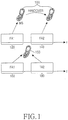
- FIG. 1 illustrates a single-frequency band support structure and a two-frequency band support structure in a conventional wireless communication system.
- a Base Station manages one or more Frequency Assignments (FAs) and provides services to Mobile Stations (MSs) in the FA or FAs.
- FAs Frequency Assignments
- MSs Mobile Stations
- an MS 100 can move from a first FA 120 (FA1) to a second FA 140 (FA2). If the MS 100 operates in only one FA or the two FAs 120 and 140 are operated by different BSs, the MS 100 receives a service in FA2 by inter-FA handover.
- FA1 first FA 120
- FA2 second FA 140
- an MS 150 As compared to the MS 100, if an MS 150 is capable of operating in two or more FAs or the same BS operates two FAs 160 and 180 (FA1 and FA2), the MS 150 can receive a service in the FAs 160 and 180. Transmission and reception of signals between the MS and the BS in multiple frequency bands facilitates high-speed, large-data data transmission and reception. However, no procedures have been agreed between the MS and the MS so far for using multiple frequency bands between them. Moreover, there is no technique for specifying an FA in which the MS will communicate after an inter-FA handover or network entry and network re-entry.
- US2005/0197133 A1 relates to a base station requesting a mobile station to change its FA from a first FA to a second FA.
- An aspect of exemplary embodiments of the present invention is to address at least the problems and/or disadvantages and to provide at least the advantages described below.
- the invention is defined in the independent claims. Preferred embodiments are defined in the dependent claims.
- Exemplary embodiments of the present invention provide a method and system for transmitting and receiving data in a plurality of frequency bands between a BS and an MS in a wireless communication system.
- the MS performs network entry or network re-entry by switching between an initial access frequency band and a primary band.
- the frequency bands can be FAs.
- the initial access frequency band (hereinafter, default FA) is a FA that the MS uses during an initial access to the BS. That is, the MS communicates with the BS, starting from contention-based initial ranging to the BS in the default FA.
- the primary band (hereinafter, primary FA) is a main FA that the MS uses for communications with the BS among the plurality of FAs.
- the primary FA usually delivers control information required for data transmission to and reception from the BS.
- the MS performs initial ranging in the default FA and uses the default FA as the primary FA after the initial ranging.
- an overlay mode is defined as a mode in which the MS and the BS can exchange data in a plurality of FAs.
- the overlay mode will be described in the context of an IEEE 802.16 communication system, for example, although the present invention is also applicable to other communication systems such as Mobile Worldwide Interoperability for Microwave Access (WiMAX) and Mobile WiMAX evolution.
- WiMAX Mobile Worldwide Interoperability for Microwave Access
- WiMAX evolution Mobile Worldwide Interoperability for Microwave Access
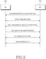
- FIG. 2 is a signal diagram illustrating an initial network entry procedure for supporting the overlay mode.
- an MS 250 acquires synchronization to a BS 200 in a particular FA in step 201.
- the BS 200 and the MS 250 perform initial ranging by exchanging ranging messages in step 203.
- the MS 250 transmits a Subscriber station Basic Capability REQuest (SBC-REQ) message to the BS 200 in step 205.
- SBC-REQ Subscriber station Basic Capability REQuest
- the SBC-REQ message may include information indicating whether the MS supports the overlay mode and, if the MS supports the overlay mode, information about the maximum number of supported FAs.
- the information can be included in a REGistration REQuest (REG-REQ) message during registration or any other control message related to the network entry.
- the BS 200 replies to the MS 250 with a Subscriber station Basic Capability ReSPonse (SBC-RSP) message in step 207.
- the SBC-RSP message may include information indicating whether the BS supports the overlay mode and, if the BS supports the overlay mode, information about the number of FAs supported by the BS 200.
- the SBC-RSP message may further include information about all FA indexes managed by the BS 200, information about the center frequency of each FA, and synchronization information.
- the SBC-RSP message may further include information about only part of the FAs, that is, only as many FAs as supported by the MS 250.
- the information included in the SBC-RSP message can be included in a REGistration ReSPonse (REG-RSP) message used during the registration or any other message related to the network entry, instead of the SBC-RSP message.
- REG-RSP REGistration ReSPonse
- the BS 200 and the MS 250 perform authentication and registration.
- an MS that is in data communication with the BS in one or more FAs may need an FA change procedure.
- the MS should receive FA information from the BS.
- the BS can make a decision as to whether the MS needs to change its current FAs and as to which FAs are suitable for the MS, based on the quality measurement of each FA reported by the MS.
- the MS can report the quality measurement of each used FA on a Channel Quality Indictor CHannel (CQICH) allocated for the FA, or by a report message.
- CQICH Channel Quality Indictor CHannel
- the BS can control the MS to report the quality measurements of FAs unused for communications between the BS and the MS.
- FIG. 3 is a signal diagram illustrating an operation for providing FA information by the BS in a wireless communication system according to an exemplary embodiment of the present invention.
- a BS 300 determines whether to transmit and receive data to and from an MS 350 in a plurality of FAs in step 302.
- the BS 300 may determine to change FAs of the MS 350 according to a system-set rule in step 302 if the MS 350 is already communicating with the BS 300 in a plurality of FAs.
- the BS 300 selects all or part of its current managed FAs in step 304. The selection is made taking into account the number of FAs supported by the MS 350.
- the BS 300 transmits to the MS 350 the indexes of the selected FAs and information about a start frame in which to start data transmission and reception in the selected FAs.
- the BS 300 may transmit to the MS 350 information about the index of an FA added to existing FAs used between the MS 350 and the BS 300 and information about a start frame in which to start data transmission and reception in the added FA.
- the BS 300 may transmit to the MS 350 information about FAs which will not be used any longer among the existing FAs used between the BS 300 and the MS 350 and information about a time when the use of the FAs is discontinued.
- the BS 300 can transmit to the MS 350 information about the index of the new FA and information about a time when data transmission and reception start in the new FA.
- the MS 350 acquires the FA information, that is, the FA indexes and the start frame information in step 308 and transmits and receives data to and from the BS 300 in the selected FAs in step 310.
- the MS 350 may signal to the BS 300 in the selected FAs that it is ready for data transmission and reception in the selected FAs.
- the BS 300 provides the FA information about the added FA (additional FA information), i.e. an FA index and start frame information to the MS 350 during network entry or upon completion of the network entry in the procedure of FIG. 3 by an SBC-RSP message, an REG-RSP message, or any other message related to the network entry, which carries FA information about the BS in the procedure of FIG. 2 .
- additional FA information i.e. an FA index and start frame information
- SBC-RSP message i.e. an FA index and start frame information
- REG-RSP message REG-RSP message
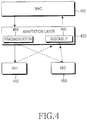
- FIG. 4 illustrates a protocol stack for supporting a plurality of FAs according to an exemplary embodiment of the present invention.
- a Medium Access Control (MAC) layer 400 performs MAC-layer operations defined in IEEE 802.16. That is, the MAC layer 400 converts data received from an upper layer to MAC-layer data and processes the MAC-layer data by mapping of an associated Connection Identifier (CID), band allocation, connection setup, connection maintenance, and MAC-layer data transmission scheduling.
- CID Connection Identifier
- An adaptation layer 420 controls data transmission and reception in each FA when an MS transmits and receives data in a plurality of FAs.
- a physical layer includes first and second Radio Frequency (RF) modules 440 and 460 (RF1 and RF2).
- RF1 and RF2 transmit and receive physical-layer data in FAs.
- the adaptation layer 420 will be described in more detail.
- the adaptation layer 420 is under the MAC layer 400. It may include a fragmentation module 480 for fragmenting the MAC-layer data for transmission to RF1 connected to FA1 and RF2 connected to FA2, and an assembly module 490 for assembling physical-layer data received from RF1 and RF2 and transmitting the assembled data to the MAC layer 400.
- the adaptation layer 420 also determines an FA in which fragmented data is to be transmitted and received, manages control information about the quality measurement or transmit power of each FA, and manages ordering of the fragmented data.
- the adaptation layer 420 should manage fragmentation information and assembly information about data. For example, when data is fragmented and transmitted in a plurality of FAs, the adaptation layer 420 can include FA index information in data to indicate an FA in which the data is transmitted or transmit the data in an FA according to a preset order without including the FA index information in the data. If the BS transmits FA information to the MS by an SBC-RSP message, for example, data can be transmitted and received in an FA order indicated by the SBC-RSP message.
- CIDs are allocated to the MS in a conventional manger irrespective of FAs used for the MS. That is, a basic CID, a primary management CID, and a secondary management CID are allocated to the MS during initial network entry.
- the MS may further be allocated a transport CID. As described before, even when an FA of the MS is changed, a connection of the MS can be identified by a CID allocated to the MS.
- an FA in which the MS performs the initial network entry, a preset FA between the BS and the MS, or an explicitly signaled FA is set as a primary FA and the primary FA can be used for controlling each of the plurality of FAs or for transmission of signals for controlling the MS except data transmission in each FA.
- the BS can set any other FA than the primary FA as a new primary FA for communications with the MS.
- the new primary FA can be used for controlling each of the plurality of FAs or for transmission of signals for controlling the MS except data transmission in each FA.
- the primary FA can be changed according to the procedure illustrated in FIG. 3 .
- FIG. 5 is a diagram illustrating a signal flow for a handover operation of an MS supporting a plurality of FAs according to an exemplary embodiment of the present invention.
- a first BS 510 is a serving BS for an MS 500 and second and third BSs 520 and 530 (BS2 and BS3) are neighbor BSs to the serving BS 510.
- a primary FA and a secondary FA for each BS are set from the perspective of the MS 500.
- FAs that the MS 500 has selected from among a plurality of FAs can be a primary FA and a secondary FA and the MS operates in the selected FAs.
- the primary FA and the secondary FA that the MS 500 uses with BS1 may be in the same band as or in different bands from those of BS2 after handover.
- the BS1 exchanges BS information with BS2 and BS3 in step 501.
- the BS information of a BS may include information about FAs that the BS manages.
- BS1 forms a neighbor BS information message including the FA information of BS2 and BS3 and transmits the neighbor BS information message to the MS 500 in the primary FA in step 503.
- the MS 500 scans the FAs managed by BS1, BS2 and BS3 based on the neighbor BS information message in step 505.
- the MS 500 transmits a handover request message in the primary FA to BS1 according to the scanning result in step 507. It is assumed herein that the handover request message indicates BS2 as an MS-selected target BS. A plurality of BSs can be selected as target BSs.
- the BS1 exchanges information with BS 2 in step 509.
- the information may include information indicating whether the MS 500 supports the overlay mode, the maximum number of FAs supported by the MS 500, and service level information about the MS 500.
- the service level information is about a service level that the MS 500 can achieve when BS1 transmits data in all FAs used for communications between BS1 and the MS 500 and a service level that the MS 500 can achieve when BS2 transmits data in all FAs supported for the MS 500.
- BS1 transmits a handover response message including the information exchanged with BS2 to the MS 500 in the primary FA in step 511.
- the MS 500 transmits to BS1 a handover indication message indicating that it will perform a handover to BS2 in step 513.
- BS1 transmits information about a context of the MS 500 to BS2. While not shown, the MS 500 and BS2 perform network re-entry. Meanwhile, the context information can be exchanged between BS1 and BS2 during the network re-entry.
- the MS 500 may receive from BS2 information about whether the overlay mode will be used, and if the overlay mode will be used, information about a primary FA, the number of FAs supported in the overlay mode, FA information such as the indexes of the FAs or the central frequencies of the FAs, and a start frame in which the overlay mode starts.
- the MS 500 transmits and receives data in the primary FA and a secondary FA to and from BS2 as indicated by BS2. Meanwhile, the MS 500 can exchange FA information for use in a final target BS during the network re-entry.
- BS2 provides the MS 500 with the FA information for use in the overlay mode and the start frame information for the overlay mode in the above description
- the MS 500 determines to perform the overlay mode using the FA information received from BS2 and notifies BS2 that the overlay mode will be performed, rather than BS2 transmits the start frame information to the MS 500.
- the notification can be transmitted in the primary FA or a secondary FA in which the overlay mode will be performed.
- the MS 500 requests the handover.
- BS1 can request the handover.
- the handover is performed similarly to the procedure of FIG. 5 , except that BS1 requests the handover to the MS 500.
- the secondary FA can be replaced with a new secondary FA. If the MS does not receive a satisfactory communication service due to the decreased signal quality of the secondary FA, the BS can request a handover to another BS to the MS.
- the MS completes ranging in a predetermined default FA. Yet, no procedure for determining an FA in which signals are to be transmitted and received after the ranging has been specified. In this context, a method for transmitting and receiving signals to and from the BS by the MS after the ranging will be described below.
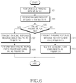
- FIG. 6 is a flowchart of an operation for commanding the MS to change a default FA in the BS according to an exemplary embodiment of the present invention.
- the BS performs code ranging with the MS in a default FA that the MS has arbitrarily selected, FA1 in step 601.
- the BS receives an initial ranging request message from the MS in FA1 in step 603.
- the initial ranging request message may include information about whether the MS supports the overlay mode. In the present invention, it is assumed that the MS can transmit and receive signals in the overlay mode.
- the BS determines whether the F1 can be used as a primary FA for the MS. The determination is made taking into account load balancing among a plurality of FAs or the processing overload of the MS. For example, if FA1 is in use as a primary FA for more MSs than a predetermined number, relative to other FAs of the BS, the BS should command the MS to use any other FA as the primary FA. That is, if the BS determines to use FA1 as the primary FA for the MS in step 605, it goes to step 607. Otherwise, the BS goes to step 611.
- the BS transmits to the MS a ranging response message including information indicating FA1 as the primary FA of the MS in step 607 and performs the remaining network entry procedure in the default FA, FA1 in step 609. During the remaining network entry procedure, the BS provides the MS with information about a secondary FA for the MS. Upon completion of the network entry, the MS transmits and receives signals using the primary FA being FA1 and the secondary FA in the overlay mode.
- the BS transmits to the MS a ranging response message including information indicating a new FA as the primary FA of the MS in step 611 and re-starts the network entry in the new FA in step 613. That is, the MS restarts the network entry in the new FA, starting from initial code ranging.
- the new FA can be at once a default FA and a primary FA.
- FIG. 7 is a flowchart illustrating a network entry operation of the MS when the MS receives a default FA change command according to an exemplary embodiment of the present invention.
- the MS performs initial code ranging to the BS using FA1 as a default FA in step 701 and transmits a ranging request message to the BS in FA1 in step 703.
- the ranging request message includes information indicating whether the MS supports the overlay mode. Further, the ranging request message may include information about the number of FAs supported by the MS. The information about the number of supported FAs can be transmitted by an SBC-REQ message during network entry.
- the MS receives a ranging response message in FA1 from the BS.
- the MS determines whether the ranging response message includes information indicating FA1 as a primary FA in step 707. If the information indicating FA1 as a primary FA is included, the MS performs the remaining network entry procedure in FA1 in step 709. If information indicating another FA as a primary FA is included, the MS re-starts an initial network entry procedure in the new FA in step 711. Thus, the MS should restart from initial code ranging to the BS in the new FA.
- FIG. 8 is a flowchart of an operation for commanding the MS to change a default FA in the BS according to another exemplary embodiment of the present invention.
- the BS performs initial ranging with the MS in a default FA FA1 in step 801 and receives an SBC-REQ message from the MS in FA1 in step 803.
- the SBC-REQ message includes information indicating whether the MS supports the overlay mode. It is assumed in FIG. 8 that the MS supports the overlay mode.
- the BS determines whether to use FA1 as a primary FA for the MS, taking into account load balancing among FAs. If the BS determines to use FA1 as the primary FA of the MS, it transmits an SBC-RSP message including information indicating FA1 as the primary FA to the MS in step 807.
- the SBC-RSP message may include information about a secondary FA for the overlay mode of the MS.
- the BS performs the remaining network entry procedure in FA1. Then, the BS transmits and receives signals to and from the MS using FA1 and the secondary FA in the overlay mode.
- the BS determines to use a new FA as the primary FA of the MS in step 805, it transmits an SBC-RSP message including information about the new FA to the MS in step 811 and re-starts network entry with the MS in the new FA in step 813. That is, the BS re-starts from initial code ranging with the MS in the new FA.
- FIG. 9 is a flowchart of a network entry operation of the MS when the MS receives a default FA change command according to another exemplary embodiment of the present invention.
- the MS performs initial ranging with the BS in a default bad, FA1 in step 901 and transmits an SBC-REQ message to the BS in FA1 in step 903.
- the MS receives an SBC-RSP message from the BS.
- step 907 the MS determines whether the SBC-RSP message includes information commanding change of the default FA from FA1 to a new FA. If there is no need to change the default FA, FAs1, the MS continues the network entry with the BS in FA1 in step 909. On the other hand, if the MS is to change the default FA from FA1 to a new FA, it re-starts the network entry, starting from initial ranging in the new FA indicated by the BS in step 911.
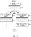
- FIG. 10 is a flowchart of an operation for commanding the MS to change a default FA in the BS according to a third exemplary embodiment of the present invention.
- the BS performs initial ranging with the MS in a default FA of the MS, FA1 in step 1001 and receives an SBC-REQ message from the MS in FA1 in step 1003.
- the SBC-REQ message may include information indicating whether the MS supports the overlay mode. It is assumed in FIG. 10 that the MS supports the overlay mode.
- the BS determines whether to use FA1 as a primary FA for the MS, taking into account load balancing among FAs. If the BS determines to use FA1 as the primary FA of the MS, it transmits an SBC-RSP message including information indicating FA1 as the primary FA to the MS in step 1007.
- the SBC-RSP message may include information about a secondary FA for the overlay mode of the MS.
- the BS performs the remaining network entry procedure in FA1.
- the BS determines to change the default FA in step 1005, it transmits an SBC-RSP message including information about a new FA as the primary FA to the MS in step 1011 and receives a signal indicating that the MS is ready for communications using the new FA as the default FA and the primary FA from the MS in step 1013.
- the BS performs the remaining network entry procedure with the MS in the new FA.
- the BS determines to change the default FA of the MS and provides information about a new FA as the default FA to the MS in step 1005, it can notify the MS of at least one of a ranging code or a ranging transmission area carrying the ranging code for use in ranging in the new default FA.
- the MS can perform ranging in the new FA using at least one of the ranging code and the ranging transmission area. This ranging is fast ranging different from contention-based initial ranging.
- the allocated ranging code or ranging transmission area information facilitates fast ranging in the new default FA in the MS, and can be used for the MS to notify the BS of an access to the BS after changing the default FA as indicated by the BS.
- FIG. 11 is a flowchart of a network entry operation of the MS when the MS receives a default FA change command according to a third exemplary embodiment of the present invention.
- the MS performs initial ranging with the BS in a default bad, FA1 in step 1101 and transmits an SBC-REQ message to the BS in FA1 in step 1103.
- the MS receives an SBC-RSP message from the BS.
- the MS determines whether the SBC-RSP message includes information commanding change of the default FA from FA1 to a new FA. If there is no need to change the default FA FAs1, the MS continues the network entry with the BS in FA1 in step 1109.
- the MS performs ranging in the new FA indicated by the BS in step 1111 and notifies the BS that it is ready for communications in the new FA as the primary FA in step 1113.
- the notification can be made by a bandwidth request header with a bandwidth request field set to 0.
- the MS performs the remaining network entry with the BS in the new FA.
- the present invention advantageously enables transmission and reception of a large amount of data by supporting multiple FAs to an MS in a wireless communication system.
Description
- The present invention generally relates to a wireless communication system. More particularly, the present invention relates to a method and system for transmitting and receiving a signal in multiple frequency bands.
- The development of wireless communication systems is a driving force behind increasing demands for various types of services and a large amount of service data. To satisfy the demands, broadband wireless communication systems have emerged. Limited frequency resources of the wireless communication systems leads to limited frequency bands available to the broadband wireless communication systems. Nevertheless, the demand for frequency bands is increasing to provide broadband services.
-
FIG. 1 illustrates a single-frequency band support structure and a two-frequency band support structure in a conventional wireless communication system. - In a wireless communication system, particularly a broadband wireless communication system based on Institute of Electrical and Electronics Engineers (IEEE) 802.16, a Base Station (BS) manages one or more Frequency Assignments (FAs) and provides services to Mobile Stations (MSs) in the FA or FAs.
- Referring to
FIG. 1 , anMS 100 can move from a first FA 120 (FA1) to a second FA 140 (FA2). If the MS 100 operates in only one FA or the twoFAs - As compared to the MS 100, if an MS 150 is capable of operating in two or more FAs or the same BS operates two
FAs 160 and 180 (FA1 and FA2), the MS 150 can receive a service in theFAs -
US2005/0197133 A1 relates to a base station requesting a mobile station to change its FA from a first FA to a second FA. - An aspect of exemplary embodiments of the present invention is to address at least the problems and/or disadvantages and to provide at least the advantages described below. The invention is defined in the independent claims. Preferred embodiments are defined in the dependent claims.
- The above and other objects, features and advantages of certain exemplary embodiments of the present invention will be more apparent from the following detailed description taken in conjunction with the accompanying drawings, in which:
-
FIG. 1 illustrates a single-frequency band support structure and a two-frequency band support structure in a conventional wireless communication system; -
FIG. 2 is a signal diagram illustrating an initial network entry procedure for supporting an overlay mode; -
FIG. 3 is a signal diagram illustrating an operation for providing FA information by a BS in a wireless communication system according to an exemplary embodiment of the present invention; -
FIG. 4 illustrates a protocol stack for supporting a plurality of FAs according to an exemplary embodiment of the present invention; -
FIG. 5 is a diagram illustrating a signal flow for a handover operation of an MS supporting a plurality of FAs according to an exemplary embodiment of the present invention; -
FIG. 6 is a flowchart of an operation for commanding the MS to change a default FA in the BS according to an exemplary embodiment of the present invention; -
FIG. 7 is a flowchart illustrating a network entry operation of the MS when the MS receives a default FA change command according to an exemplary embodiment of the present invention; -
FIG. 8 is a flowchart of an operation for commanding the MS to change a default FA in the BS according to another exemplary embodiment of the present invention; -
FIG. 9 is a flowchart of a network entry operation of the MS when the MS receives a default FA change command according to another exemplary embodiment of the present invention; -
FIG. 10 is a flowchart of an operation for commanding the MS to change a default FA in the BS according to a third exemplary embodiment of the present invention; and -
FIG. 11 is a flowchart of a network entry operation of the MS when the MS receives a default FA change command according to a third exemplary embodiment of the present invention. - Throughout the drawings, the same drawing reference numerals will be understood to refer to the same elements, features and structures.
- The matters defined in the description such as a detailed construction and elements are provided to assist in a comprehensive understanding of exemplary embodiments of the invention. Accordingly, those of ordinary skill in the art will recognize that various changes and modifications of the embodiments described herein can be made without departing from the scope of the invention. Also, descriptions of well-known functions and constructions are omitted for clarity and conciseness.
- Exemplary embodiments of the present invention provide a method and system for transmitting and receiving data in a plurality of frequency bands between a BS and an MS in a wireless communication system. For this purpose, the MS performs network entry or network re-entry by switching between an initial access frequency band and a primary band. The frequency bands can be FAs.
- The initial access frequency band (hereinafter, default FA) is a FA that the MS uses during an initial access to the BS. That is, the MS communicates with the BS, starting from contention-based initial ranging to the BS in the default FA. The primary band (hereinafter, primary FA) is a main FA that the MS uses for communications with the BS among the plurality of FAs. The primary FA usually delivers control information required for data transmission to and reception from the BS. In accordance with the present invention, the MS performs initial ranging in the default FA and uses the default FA as the primary FA after the initial ranging.
- Herein, an overlay mode is defined as a mode in which the MS and the BS can exchange data in a plurality of FAs. The overlay mode will be described in the context of an IEEE 802.16 communication system, for example, although the present invention is also applicable to other communication systems such as Mobile Worldwide Interoperability for Microwave Access (WiMAX) and Mobile WiMAX evolution.
-
FIG. 2 is a signal diagram illustrating an initial network entry procedure for supporting the overlay mode. - Referring to
FIG. 2 , an MS 250 acquires synchronization to aBS 200 in a particular FA instep 201. The BS 200 and the MS 250 perform initial ranging by exchanging ranging messages instep 203. - The MS 250 transmits a Subscriber station Basic Capability REQuest (SBC-REQ) message to the
BS 200 instep 205. The SBC-REQ message may include information indicating whether the MS supports the overlay mode and, if the MS supports the overlay mode, information about the maximum number of supported FAs. The information can be included in a REGistration REQuest (REG-REQ) message during registration or any other control message related to the network entry. - The BS 200 replies to the MS 250 with a Subscriber station Basic Capability ReSPonse (SBC-RSP) message in
step 207. The SBC-RSP message may include information indicating whether the BS supports the overlay mode and, if the BS supports the overlay mode, information about the number of FAs supported by theBS 200. The SBC-RSP message may further include information about all FA indexes managed by theBS 200, information about the center frequency of each FA, and synchronization information. Or the SBC-RSP message may further include information about only part of the FAs, that is, only as many FAs as supported by theMS 250. - The information included in the SBC-RSP message can be included in a REGistration ReSPonse (REG-RSP) message used during the registration or any other message related to the network entry, instead of the SBC-RSP message.
- In
steps BS 200 and the MS 250 perform authentication and registration. - Meanwhile, an MS that is in data communication with the BS in one or more FAs may need an FA change procedure. For this purpose, the MS should receive FA information from the BS. The BS can make a decision as to whether the MS needs to change its current FAs and as to which FAs are suitable for the MS, based on the quality measurement of each FA reported by the MS. The MS can report the quality measurement of each used FA on a Channel Quality Indictor CHannel (CQICH) allocated for the FA, or by a report message. When needed, the BS can control the MS to report the quality measurements of FAs unused for communications between the BS and the MS.
-
FIG. 3 is a signal diagram illustrating an operation for providing FA information by the BS in a wireless communication system according to an exemplary embodiment of the present invention. - Referring to
FIG. 3 , aBS 300 determines whether to transmit and receive data to and from anMS 350 in a plurality of FAs instep 302. TheBS 300 may determine to change FAs of theMS 350 according to a system-set rule instep 302 if theMS 350 is already communicating with theBS 300 in a plurality of FAs. - In either of the above cases, the
BS 300 selects all or part of its current managed FAs instep 304. The selection is made taking into account the number of FAs supported by theMS 350. - In
step 306, theBS 300 transmits to theMS 350 the indexes of the selected FAs and information about a start frame in which to start data transmission and reception in the selected FAs. TheBS 300 may transmit to theMS 350 information about the index of an FA added to existing FAs used between theMS 350 and theBS 300 and information about a start frame in which to start data transmission and reception in the added FA. Also, theBS 300 may transmit to theMS 350 information about FAs which will not be used any longer among the existing FAs used between theBS 300 and theMS 350 and information about a time when the use of the FAs is discontinued. When an existing FA used for data transmission and reception is changed to a new FA, theBS 300 can transmit to theMS 350 information about the index of the new FA and information about a time when data transmission and reception start in the new FA. - The
MS 350 acquires the FA information, that is, the FA indexes and the start frame information instep 308 and transmits and receives data to and from theBS 300 in the selected FAs instep 310. - After acquiring the FA information in
step 308, theMS 350 may signal to theBS 300 in the selected FAs that it is ready for data transmission and reception in the selected FAs. - The
BS 300 provides the FA information about the added FA (additional FA information), i.e. an FA index and start frame information to theMS 350 during network entry or upon completion of the network entry in the procedure ofFIG. 3 by an SBC-RSP message, an REG-RSP message, or any other message related to the network entry, which carries FA information about the BS in the procedure ofFIG. 2 . -
FIG. 4 illustrates a protocol stack for supporting a plurality of FAs according to an exemplary embodiment of the present invention. - Referring to
FIG. 4 , a Medium Access Control (MAC)layer 400 performs MAC-layer operations defined in IEEE 802.16. That is, theMAC layer 400 converts data received from an upper layer to MAC-layer data and processes the MAC-layer data by mapping of an associated Connection Identifier (CID), band allocation, connection setup, connection maintenance, and MAC-layer data transmission scheduling. - An
adaptation layer 420 controls data transmission and reception in each FA when an MS transmits and receives data in a plurality of FAs. - A physical layer includes first and second Radio Frequency (RF)
modules 440 and 460 (RF1 and RF2). RF1 and RF2 transmit and receive physical-layer data in FAs. - The
adaptation layer 420 will be described in more detail. - The
adaptation layer 420 is under theMAC layer 400. It may include afragmentation module 480 for fragmenting the MAC-layer data for transmission to RF1 connected to FA1 and RF2 connected to FA2, and anassembly module 490 for assembling physical-layer data received from RF1 and RF2 and transmitting the assembled data to theMAC layer 400. Theadaptation layer 420 also determines an FA in which fragmented data is to be transmitted and received, manages control information about the quality measurement or transmit power of each FA, and manages ordering of the fragmented data. - As described above, the
adaptation layer 420 should manage fragmentation information and assembly information about data. For example, when data is fragmented and transmitted in a plurality of FAs, theadaptation layer 420 can include FA index information in data to indicate an FA in which the data is transmitted or transmit the data in an FA according to a preset order without including the FA index information in the data. If the BS transmits FA information to the MS by an SBC-RSP message, for example, data can be transmitted and received in an FA order indicated by the SBC-RSP message. - Meanwhile, CIDs are allocated to the MS in a conventional manger irrespective of FAs used for the MS. That is, a basic CID, a primary management CID, and a secondary management CID are allocated to the MS during initial network entry. The MS may further be allocated a transport CID. As described before, even when an FA of the MS is changed, a connection of the MS can be identified by a CID allocated to the MS. If the MS transmits and receives data in a plurality of FAs, an FA in which the MS performs the initial network entry, a preset FA between the BS and the MS, or an explicitly signaled FA is set as a primary FA and the primary FA can be used for controlling each of the plurality of FAs or for transmission of signals for controlling the MS except data transmission in each FA. The BS can set any other FA than the primary FA as a new primary FA for communications with the MS. The new primary FA can be used for controlling each of the plurality of FAs or for transmission of signals for controlling the MS except data transmission in each FA. The primary FA can be changed according to the procedure illustrated in
FIG. 3 . -
FIG. 5 is a diagram illustrating a signal flow for a handover operation of an MS supporting a plurality of FAs according to an exemplary embodiment of the present invention. - Referring to
FIG. 5 , a first BS 510 (BS1) is a serving BS for anMS 500 and second andthird BSs 520 and 530 (BS2 and BS3) are neighbor BSs to the servingBS 510. A primary FA and a secondary FA for each BS are set from the perspective of theMS 500. In other words, FAs that theMS 500 has selected from among a plurality of FAs can be a primary FA and a secondary FA and the MS operates in the selected FAs. For example, the primary FA and the secondary FA that theMS 500 uses with BS1 may be in the same band as or in different bands from those of BS2 after handover. - BS1 exchanges BS information with BS2 and BS3 in
step 501. The BS information of a BS may include information about FAs that the BS manages. - BS1 forms a neighbor BS information message including the FA information of BS2 and BS3 and transmits the neighbor BS information message to the
MS 500 in the primary FA instep 503. TheMS 500 scans the FAs managed by BS1, BS2 and BS3 based on the neighbor BS information message instep 505. - The
MS 500 transmits a handover request message in the primary FA to BS1 according to the scanning result instep 507. It is assumed herein that the handover request message indicates BS2 as an MS-selected target BS. A plurality of BSs can be selected as target BSs. - BS1 exchanges information with
BS 2 instep 509. The information may include information indicating whether theMS 500 supports the overlay mode, the maximum number of FAs supported by theMS 500, and service level information about theMS 500. The service level information is about a service level that theMS 500 can achieve when BS1 transmits data in all FAs used for communications between BS1 and theMS 500 and a service level that theMS 500 can achieve when BS2 transmits data in all FAs supported for theMS 500. - BS1 transmits a handover response message including the information exchanged with BS2 to the
MS 500 in the primary FA in step 511. As BS2 satisfies a handover condition, theMS 500 transmits to BS1 a handover indication message indicating that it will perform a handover to BS2 instep 513. - In
step 515, BS1 transmits information about a context of theMS 500 to BS2. While not shown, theMS 500 and BS2 perform network re-entry. Meanwhile, the context information can be exchanged between BS1 and BS2 during the network re-entry. - During the network re-entry, the
MS 500 may receive from BS2 information about whether the overlay mode will be used, and if the overlay mode will be used, information about a primary FA, the number of FAs supported in the overlay mode, FA information such as the indexes of the FAs or the central frequencies of the FAs, and a start frame in which the overlay mode starts. After the network re-entry, theMS 500 transmits and receives data in the primary FA and a secondary FA to and from BS2 as indicated by BS2. Meanwhile, theMS 500 can exchange FA information for use in a final target BS during the network re-entry. - While BS2 provides the
MS 500 with the FA information for use in the overlay mode and the start frame information for the overlay mode in the above description, it can be further contemplated that theMS 500 determines to perform the overlay mode using the FA information received from BS2 and notifies BS2 that the overlay mode will be performed, rather than BS2 transmits the start frame information to theMS 500. The notification can be transmitted in the primary FA or a secondary FA in which the overlay mode will be performed. - In the illustrated case of
FIG. 5 , theMS 500 requests the handover. Instead, BS1 can request the handover. In this case, the handover is performed similarly to the procedure ofFIG. 5 , except that BS1 requests the handover to theMS 500. - If the signal quality of the secondary FA is decreased during communications between the MS and the BS in the primary FA and the secondary FA, the secondary FA can be replaced with a new secondary FA. If the MS does not receive a satisfactory communication service due to the decreased signal quality of the secondary FA, the BS can request a handover to another BS to the MS.
- Conventionally, the MS completes ranging in a predetermined default FA. Yet, no procedure for determining an FA in which signals are to be transmitted and received after the ranging has been specified. In this context, a method for transmitting and receiving signals to and from the BS by the MS after the ranging will be described below.
-
FIG. 6 is a flowchart of an operation for commanding the MS to change a default FA in the BS according to an exemplary embodiment of the present invention. - Referring to
FIG. 6 , the BS performs code ranging with the MS in a default FA that the MS has arbitrarily selected, FA1 instep 601. As the coding ranging is successful, the BS receives an initial ranging request message from the MS in FA1 instep 603. The initial ranging request message may include information about whether the MS supports the overlay mode. In the present invention, it is assumed that the MS can transmit and receive signals in the overlay mode. - In
step 605, the BS determines whether the F1 can be used as a primary FA for the MS. The determination is made taking into account load balancing among a plurality of FAs or the processing overload of the MS. For example, if FA1 is in use as a primary FA for more MSs than a predetermined number, relative to other FAs of the BS, the BS should command the MS to use any other FA as the primary FA. That is, if the BS determines to use FA1 as the primary FA for the MS instep 605, it goes to step 607. Otherwise, the BS goes to step 611. - The BS transmits to the MS a ranging response message including information indicating FA1 as the primary FA of the MS in
step 607 and performs the remaining network entry procedure in the default FA, FA1 instep 609. During the remaining network entry procedure, the BS provides the MS with information about a secondary FA for the MS. Upon completion of the network entry, the MS transmits and receives signals using the primary FA being FA1 and the secondary FA in the overlay mode. - Meanwhile, the BS transmits to the MS a ranging response message including information indicating a new FA as the primary FA of the MS in
step 611 and re-starts the network entry in the new FA instep 613. That is, the MS restarts the network entry in the new FA, starting from initial code ranging. The new FA can be at once a default FA and a primary FA. -
FIG. 7 is a flowchart illustrating a network entry operation of the MS when the MS receives a default FA change command according to an exemplary embodiment of the present invention. - Referring to
FIG. 7 , the MS performs initial code ranging to the BS using FA1 as a default FA instep 701 and transmits a ranging request message to the BS in FA1 instep 703. The ranging request message includes information indicating whether the MS supports the overlay mode. Further, the ranging request message may include information about the number of FAs supported by the MS. The information about the number of supported FAs can be transmitted by an SBC-REQ message during network entry. - In
step 705, the MS receives a ranging response message in FA1 from the BS. The MS determines whether the ranging response message includes information indicating FA1 as a primary FA instep 707. If the information indicating FA1 as a primary FA is included, the MS performs the remaining network entry procedure in FA1 instep 709. If information indicating another FA as a primary FA is included, the MS re-starts an initial network entry procedure in the new FA instep 711. Thus, the MS should restart from initial code ranging to the BS in the new FA. -
FIG. 8 is a flowchart of an operation for commanding the MS to change a default FA in the BS according to another exemplary embodiment of the present invention. - Referring to
FIG. 8 , the BS performs initial ranging with the MS in a default FA FA1 instep 801 and receives an SBC-REQ message from the MS in FA1 instep 803. The SBC-REQ message includes information indicating whether the MS supports the overlay mode. It is assumed inFIG. 8 that the MS supports the overlay mode. - In
step 805, the BS determines whether to use FA1 as a primary FA for the MS, taking into account load balancing among FAs. If the BS determines to use FA1 as the primary FA of the MS, it transmits an SBC-RSP message including information indicating FA1 as the primary FA to the MS instep 807. The SBC-RSP message may include information about a secondary FA for the overlay mode of the MS. Instep 809, the BS performs the remaining network entry procedure in FA1. Then, the BS transmits and receives signals to and from the MS using FA1 and the secondary FA in the overlay mode. - Meanwhile, if the BS determines to use a new FA as the primary FA of the MS in
step 805, it transmits an SBC-RSP message including information about the new FA to the MS instep 811 and re-starts network entry with the MS in the new FA instep 813. That is, the BS re-starts from initial code ranging with the MS in the new FA. -
FIG. 9 is a flowchart of a network entry operation of the MS when the MS receives a default FA change command according to another exemplary embodiment of the present invention. - Referring to
FIG. 9 , the MS performs initial ranging with the BS in a default bad, FA1 instep 901 and transmits an SBC-REQ message to the BS in FA1 instep 903. Instep 905, the MS receives an SBC-RSP message from the BS. - In
step 907, the MS determines whether the SBC-RSP message includes information commanding change of the default FA from FA1 to a new FA. If there is no need to change the default FA, FAs1, the MS continues the network entry with the BS in FA1 instep 909. On the other hand, if the MS is to change the default FA from FA1 to a new FA, it re-starts the network entry, starting from initial ranging in the new FA indicated by the BS instep 911. -
FIG. 10 is a flowchart of an operation for commanding the MS to change a default FA in the BS according to a third exemplary embodiment of the present invention. - Referring to
FIG. 10 , the BS performs initial ranging with the MS in a default FA of the MS, FA1 instep 1001 and receives an SBC-REQ message from the MS in FA1 instep 1003. The SBC-REQ message may include information indicating whether the MS supports the overlay mode. It is assumed inFIG. 10 that the MS supports the overlay mode. - In
step 1005, the BS determines whether to use FA1 as a primary FA for the MS, taking into account load balancing among FAs. If the BS determines to use FA1 as the primary FA of the MS, it transmits an SBC-RSP message including information indicating FA1 as the primary FA to the MS instep 1007. The SBC-RSP message may include information about a secondary FA for the overlay mode of the MS. Instep 1009, the BS performs the remaining network entry procedure in FA1. - Meanwhile, if the BS determines to change the default FA in
step 1005, it transmits an SBC-RSP message including information about a new FA as the primary FA to the MS instep 1011 and receives a signal indicating that the MS is ready for communications using the new FA as the default FA and the primary FA from the MS instep 1013. Instep 1015, the BS performs the remaining network entry procedure with the MS in the new FA. - When the BS determines to change the default FA of the MS and provides information about a new FA as the default FA to the MS in
step 1005, it can notify the MS of at least one of a ranging code or a ranging transmission area carrying the ranging code for use in ranging in the new default FA. The MS can perform ranging in the new FA using at least one of the ranging code and the ranging transmission area. This ranging is fast ranging different from contention-based initial ranging. - The allocated ranging code or ranging transmission area information facilitates fast ranging in the new default FA in the MS, and can be used for the MS to notify the BS of an access to the BS after changing the default FA as indicated by the BS.
-
FIG. 11 is a flowchart of a network entry operation of the MS when the MS receives a default FA change command according to a third exemplary embodiment of the present invention. - Referring to
FIG. 11 , the MS performs initial ranging with the BS in a default bad, FA1 instep 1101 and transmits an SBC-REQ message to the BS in FA1 instep 1103. Instep 1105, the MS receives an SBC-RSP message from the BS. Instep 1107, the MS determines whether the SBC-RSP message includes information commanding change of the default FA from FA1 to a new FA. If there is no need to change the default FA FAs1, the MS continues the network entry with the BS in FA1 instep 1109. - On the other hand, if the MS is to change the default FA from FA1 to a new FA, it performs ranging in the new FA indicated by the BS in
step 1111 and notifies the BS that it is ready for communications in the new FA as the primary FA instep 1113. The notification can be made by a bandwidth request header with a bandwidth request field set to 0. Instep 1115, the MS performs the remaining network entry with the BS in the new FA. - As is apparent from the above description, the present invention advantageously enables transmission and reception of a large amount of data by supporting multiple FAs to an MS in a wireless communication system.
- While the invention has been shown and described with reference to certain exemplary embodiments of the present invention thereof, it will be understood by those skilled in the art that various changes in form and details may be made therein without departing from the scope of the present invention as defined by the appended claims and their equivalents.
Claims (15)
- A method for changing frequency assignment, FA, by a base station (300),
BS, in a wireless communication system, comprising:transmitting to a mobile station (350), MS, a FA changing message comprising index information of a second FA and time information for changing a first FA used by the MS to the second FA, which is one of a plurality of FAs managed by the BS, using the first FA; andif a response message corresponding to the FA changing message is received from the MS, changing the first FA to the second FA at a time according to the time information. - The method of claim 1, wherein changing the first FA to the second FA comprises:performing a ranging procedure with the MS on the second FA, based on a ranging indicator; andif the response message is received from the MS on the second FA, changing the first FA to the second FA at the time according to the time information,wherein the ranging indicator indicates whether to perform the ranging procedure on the second FA, and is included in the FA changing message.
- A method for changing frequency assignment, FA, by a mobile station (350),
MS, in a wireless communication system, comprising:receiving from a base station (300), BS, a FA changing message comprising index information of a second FA and time information for changing a first FA used by the MS to the second FA, which is one of a plurality of FAs managed by the BS, using the first FA; andtransmitting a response message corresponding to the FA changing message to the BS, and changing the first FA to the second FA at a time according to the time information. - The method of claim 3, wherein transmitting the response message and changing the first FA to the second FA comprises:performing a ranging procedure with the BS on the second FA, based on a ranging indicator; andif the second FA is ready, transmitting the response message to the BS, and changing the first FA to the second FA at the time according to the time information,wherein the ranging indicator indicates whether to perform the ranging procedure on the second FA, and is included in the FA changing message.
- A base station (300), BS, for changing frequency assignment, FA, in a wireless communication system, the BS comprising:a transmitter for transmitting to a mobile station (350), MS, a FA changing message comprising index information of a second FA and time information for changing a first FA used by the MS to the second FA, which is one of a plurality of FAs managed by the BS, using the first FA;a receiver for receiving a response message corresponding to the FA changing message is received from the MS; anda controller for, if the response message is received, changing the first FA to the second FA at a time according to the time information.
- The method of claim 1 or the BS of claim 5, wherein the second FA is determined based on a quality measurement value of each of the plurality of FAs reported by the MS.
- The method or the BS of claim 6, wherein the quality measurement value includes a quality measurement value of each FA used by the MS, reported by the MS on a Channel Quality Indictor CHannel, CQICH, allocated for each FA used by the MS.
- The method or the BS of claim 6, wherein the quality measurement value includes a quality measurement value of each of FAs unused for communications with the BS, reported by the MS.
- The BS of claim 5, wherein the controller performs a ranging procedure with the MS on the second FA, based on a ranging indicator, and if the response message is received from the MS on the second FA, changes the first FA to the second FA at the time according to the time information,
wherein the ranging indicator indicates whether to perform the ranging procedure on the second FA, and is included in the FA changing message. - A mobile station (350), MS, for changing frequency assignment, FA, in a wireless communication system, the MS comprising:a receiver for receiving from a base station (300), BS, a FA changing message comprising index information of a second FA and time information for changing a first FA used by the MS to the second FA, which is one of a plurality of FAs managed by the BS, using the first FA;a transmitter for transmitting a response message corresponding to the FA changing message to the BS; anda controller for changing the first FA to the second FA at a time according to the time information.
- The method of claim 3 or the MS of claim 10, wherein the second FA is determined based on a quality measurement value of each of the plurality of FAs, transmitted to the BS.
- The method or the MS of claim 11, wherein the quality measurement value includes a quality measurement value of each FA used by the MS, reported to the BS on a channel quality indictor channel, CQICH, allocated for each FA used by the MS.
- The method or the MS of claim 11, wherein the quality measurement value includes a quality measurement value of each of FAs unused for communications with the BS, reported to the BS.
- The method of claim 1 or claim 3 or the BS of claim 5 or the MS of claim 10, wherein FA changing message is one of a subscriber basic capability response, SBC-RSP, message, a registration response, REG-RSP, message and another message related to a network entry.
- The MS of claim 10, wherein the controller is arranged to perform a ranging procedure with the BS on the second FA, based on a ranging indicator, if the second FA is ready, to transmit the response message to the BS by controlling the transmitter, and to change the first FA to the second FA at the time according to the time information,
wherein the ranging indicator indicates whether to perform the ranging procedure on the second FA, and is included in the FA changing message.
Applications Claiming Priority (5)
| Application Number | Priority Date | Filing Date | Title |
|---|---|---|---|
| KR20070004039 | 2007-01-13 | ||
| KR20070011170 | 2007-02-02 | ||
| KR20070039063 | 2007-04-20 | ||
| KR20070045242 | 2007-05-09 | ||
| PCT/KR2008/000196 WO2008085009A1 (en) | 2007-01-13 | 2008-01-11 | Method and system for transmitting and receiving signal using multiple frequency bands in a wireless communication system |
Publications (3)
| Publication Number | Publication Date |
|---|---|
| EP2109944A1 EP2109944A1 (en) | 2009-10-21 |
| EP2109944A4 EP2109944A4 (en) | 2013-11-06 |
| EP2109944B1 true EP2109944B1 (en) | 2017-03-08 |
Family
ID=39608849
Family Applications (1)
| Application Number | Title | Priority Date | Filing Date |
|---|---|---|---|
| EP08704735.3A Active EP2109944B1 (en) | 2007-01-13 | 2008-01-11 | Method and system for transmitting and receiving signals using multiple frequency bands in a wireless communication system |
Country Status (6)
| Country | Link |
|---|---|
| US (1) | US10014931B2 (en) |
| EP (1) | EP2109944B1 (en) |
| JP (2) | JP4976505B2 (en) |
| KR (1) | KR100973433B1 (en) |
| CN (1) | CN103346831B (en) |
| WO (1) | WO2008085009A1 (en) |
Families Citing this family (21)
| Publication number | Priority date | Publication date | Assignee | Title |
|---|---|---|---|---|
| CN103346831B (en) * | 2007-01-13 | 2017-10-10 | 三星电子株式会社 | The method and system of signal is sent and received in wireless communication system using multiple frequency bands |
| US8676208B2 (en) * | 2008-06-11 | 2014-03-18 | Mediatek Inc. | Scanning and handover operation in multi-carrier wireless communications systems |
| KR101199400B1 (en) * | 2008-07-08 | 2012-11-12 | 엘지전자 주식회사 | Method for generating a carrier group and method for transmitting carrier group information |
| WO2010016255A1 (en) | 2008-08-06 | 2010-02-11 | シャープ株式会社 | Communication system, mobile station device, and communication method |
| KR101682034B1 (en) * | 2008-08-18 | 2016-12-05 | 삼성전자주식회사 | Apparatus and method for using secondary frequency assignment optionnally in a wireless communication system using multiple band |
| US8401541B2 (en) | 2008-09-05 | 2013-03-19 | Electronics And Telecommunications Research Institute | Method and apparatus for scanning in multi-carrier communication system |
| US8804631B2 (en) | 2009-03-02 | 2014-08-12 | Mediatek Inc. | Method and apparatus for communicating carrier configuration in multi-carrier OFDM systems |
| CN101848501B (en) * | 2009-03-27 | 2014-01-01 | 中兴通讯股份有限公司 | Method and base station for realizing carrier aggregation |
| KR101918026B1 (en) * | 2009-04-22 | 2018-11-13 | 삼성전자주식회사 | Method and apparatus for supporting multiple frequency assignment in wireless communication system |
| EP2422544A4 (en) * | 2009-04-24 | 2016-01-06 | Mediatek Inc | Carrier assignment with mobility support in multi-carrier ofdm systems |
| JP5666572B2 (en) * | 2009-06-17 | 2015-02-12 | テレフオンアクチーボラゲット エル エム エリクソン(パブル) | Scheduling data transmission between a mobile terminal and a base station in a wireless communication network |
| KR101643731B1 (en) | 2009-08-11 | 2016-07-29 | 삼성전자주식회사 | Apparatus and method for multiple fa reception in mobile communication system |
| KR101405454B1 (en) * | 2009-09-21 | 2014-06-11 | 한국전자통신연구원 | Method for handover in multi-carrier system |
| CN102045862B (en) * | 2009-10-22 | 2014-10-01 | 中国移动通信集团公司 | Carrier aggregation realizing method, device and system |
| WO2011052643A1 (en) | 2009-10-29 | 2011-05-05 | 日本電気株式会社 | Wireless communication system, wireless communication method, wireless station, and program |
| US9240869B2 (en) * | 2009-11-25 | 2016-01-19 | Sharp Kabushiki Kaisha | Wireless communication system |
| JP5048746B2 (en) | 2009-12-09 | 2012-10-17 | シャープ株式会社 | Communication system, mobile station apparatus, radio link state management method, and integrated circuit |
| JP6230516B2 (en) * | 2014-10-08 | 2017-11-15 | シャープ株式会社 | Base station apparatus, mobile station apparatus, and processing method |
| CN105628795B (en) * | 2015-12-24 | 2018-10-02 | 哈尔滨工业大学 | The method for carrying out welding line ultrasonic detection using frequency plot composite coding pumping signal |
| BR112018077043A2 (en) * | 2016-06-30 | 2019-04-02 | Huawei Tech Co Ltd | computer readable frequency band and storage medium processing method and apparatus |
| KR102260297B1 (en) * | 2020-01-13 | 2021-06-03 | 국방과학연구소 | Wireless communication system and operating method for the same |
Family Cites Families (58)
| Publication number | Priority date | Publication date | Assignee | Title |
|---|---|---|---|---|
| JP2841900B2 (en) * | 1991-02-27 | 1998-12-24 | 日本電気株式会社 | Handoff method |
| US5384777A (en) * | 1993-04-19 | 1995-01-24 | International Business Machines Corporation | Adaptive medium access control scheme for wireless LAN |
| CA2191437C (en) * | 1994-06-02 | 2003-11-18 | John M. Cioffi | Method and apparatus for coordinating multi-point-to-point communications in a multi-tone data transmission system |
| DE69433872T2 (en) * | 1994-10-26 | 2005-07-14 | International Business Machines Corp. | Medium access control scheme for wireless local area networks with interleaved variable length time division frames |
| FI103850B (en) * | 1996-07-12 | 1999-09-30 | Nokia Mobile Phones Ltd | Automatic control of communication mode |
| US6519457B1 (en) * | 1997-04-09 | 2003-02-11 | Nortel Networks Limited | Methods and systems for standardizing interbase station communications |
| US5940763A (en) * | 1997-04-23 | 1999-08-17 | Ericsson, Inc. | Enhanced preemption within a mobile telecommunications network |
| FI109513B (en) * | 1997-05-13 | 2002-08-15 | Nokia Corp | Cell load based handover on mobile communication systems |
| US6829477B1 (en) * | 1997-08-27 | 2004-12-07 | Interwave Communications International, Ltd. | Private multiplexing cellular network |
| US6038450A (en) * | 1997-09-12 | 2000-03-14 | Lucent Technologies, Inc. | Soft handover system for a multiple sub-carrier communication system and method thereof |
| KR100277058B1 (en) * | 1998-06-15 | 2001-01-15 | 윤종용 | A method for deciding the starting time of inter-frequency hard handoff and a method for initiating of hard handoff in mobile telecommunication system |
| KR100291478B1 (en) * | 1998-09-08 | 2001-06-01 | 윤종용 | Method and system for idle handoff in cellular system |
| US6963545B1 (en) * | 1998-10-07 | 2005-11-08 | At&T Corp. | Voice-data integrated multiaccess by self-reservation and stabilized aloha contention |
| US6684120B1 (en) | 1998-12-03 | 2004-01-27 | Bridgestone Corporation | Method of and device for collecting and combining FA information |
| US6985455B1 (en) * | 2000-03-03 | 2006-01-10 | Hughes Electronics Corporation | Method and system for providing satellite bandwidth on demand using multi-level queuing |
| US6738350B1 (en) * | 2000-03-16 | 2004-05-18 | Hughes Electronics Corporation | Congestion avoidance approach for a switching communication system with transmission constraints |
| US6947748B2 (en) * | 2000-12-15 | 2005-09-20 | Adaptix, Inc. | OFDMA with adaptive subcarrier-cluster configuration and selective loading |
| KR100592597B1 (en) * | 2001-01-10 | 2006-06-26 | 한국전자통신연구원 | A Method for Handover using Compressed Mode and Common Frequency between Neighbor Cells |
| US7206840B2 (en) * | 2001-05-11 | 2007-04-17 | Koninklike Philips Electronics N.V. | Dynamic frequency selection scheme for IEEE 802.11 WLANs |
| US7027414B2 (en) * | 2001-08-09 | 2006-04-11 | Hughes Network Systems, Llc | Method, apparatus, and system for identifying and efficiently treating classes of traffic |
| US7085247B2 (en) * | 2001-08-09 | 2006-08-01 | Hughes Network Systems, Llc | Scheduling and queue servicing in a satellite terminal for bandwidth allocations in a broadband satellite communications system |
| FI114275B (en) * | 2002-05-31 | 2004-09-15 | Nokia Corp | Control of handover between frequencies |
| EP1574097A1 (en) | 2002-12-19 | 2005-09-14 | Nokia Corporation | System and handover mechanism in frequency multiple band environment and equipment therefor |
| KR100594110B1 (en) * | 2003-03-08 | 2006-07-03 | 삼성전자주식회사 | System and method for implementing a handoff in a traffic state in a broadband wireless access communication system |
| JP4211529B2 (en) | 2003-08-06 | 2009-01-21 | 日本電気株式会社 | Channel selection method and radio station and program used therefor |
| KR100689508B1 (en) * | 2003-09-04 | 2007-03-02 | 삼성전자주식회사 | Method for performing handover in a communication system |
| US7643449B2 (en) * | 2005-01-18 | 2010-01-05 | Airwalk Communications, Inc. | Combined base transceiver station and base station controller data call and quality of service |
| US20050159162A1 (en) * | 2004-01-20 | 2005-07-21 | Samsung Electronics Co., Ltd. | Method for transmitting data in mobile communication network |
| KR20050089685A (en) * | 2004-03-05 | 2005-09-08 | 삼성전자주식회사 | System and method for changing frequency allocation in a broadband wireless access communication system |
| KR100810247B1 (en) * | 2004-03-05 | 2008-03-06 | 삼성전자주식회사 | Method and apparatus for allocation of channel in a orthogonal frequency division multiple access system |
| KR20050109863A (en) * | 2004-05-17 | 2005-11-22 | 삼성전자주식회사 | Dynamic subchannel and bit allocation in multiuser mimo/ofdma system |
| US7839820B2 (en) * | 2004-05-21 | 2010-11-23 | Samsung Electronics Co., Ltd. | Mobile station and method for implementing variable bandwidth service on demand |
| JP4095585B2 (en) | 2004-06-17 | 2008-06-04 | 株式会社東芝 | Wireless communication method, wireless communication device, and wireless communication system |
| KR100703517B1 (en) * | 2004-06-19 | 2007-04-03 | 삼성전자주식회사 | System and method for allocating a safety channel in a broadband wireless access communication system |
| US7689247B2 (en) * | 2004-06-30 | 2010-03-30 | Motorola, Inc | Method and apparatus for radio frequency band assignment in a wireless communication system |
| US20060013182A1 (en) * | 2004-07-19 | 2006-01-19 | Telefonaktiebolaget Lm Ericsson | Selective multicarrier CDMA network |
| KR100895184B1 (en) * | 2004-08-04 | 2009-04-24 | 삼성전자주식회사 | Method and System for handoff between Base station Supporting Multi-Profile Operation in Broadband Wireless Access System |
| KR100856248B1 (en) * | 2004-08-17 | 2008-09-03 | 삼성전자주식회사 | METHOD FOR SCHEDULING UPLINK IN VoIP |
| US20060056344A1 (en) | 2004-09-10 | 2006-03-16 | Interdigital Technology Corporation | Seamless channel change in a wireless local area network |
| KR100617732B1 (en) * | 2004-10-26 | 2006-08-28 | 삼성전자주식회사 | Method and system for transmitting and receiving neighbor base station advertisement information message in mobile communication system |
| CN101795185B (en) | 2004-11-03 | 2012-08-15 | 三星电子株式会社 | System and method for transmitting/receiving hybrid automatic repeat request buffer capability information in broadband wireless access communication system |
| US20060166677A1 (en) | 2005-01-27 | 2006-07-27 | Lucent Technologies, Inc. | Balancing load of cells in inter-frequency handover of wireless communications |
| TW200642503A (en) * | 2005-03-03 | 2006-12-01 | Nokia Corp | A method to handover dedicated and shared resources while in dual transfer mode |
| EP2252106B1 (en) * | 2005-03-28 | 2019-12-25 | Sony Corporation | Mobile communications system, handover controlling method, radio network controller, and mobile terminal |
| CN101156421A (en) | 2005-04-01 | 2008-04-02 | 美商内数位科技公司 | Method and apparatus for selecting a multi-band access pointto associate with a multi-band mobile station |
| US7797018B2 (en) | 2005-04-01 | 2010-09-14 | Interdigital Technology Corporation | Method and apparatus for selecting a multi-band access point to associate with a multi-band mobile station |
| US7957351B2 (en) * | 2005-04-04 | 2011-06-07 | Qualcomm Incorporated | Method and apparatus for management of multi-carrier communications in a wireless communication system |
| US7715842B2 (en) * | 2005-04-09 | 2010-05-11 | Lg Electronics Inc. | Supporting handover of mobile terminal |
| KR101002879B1 (en) * | 2005-06-10 | 2010-12-21 | 삼성전자주식회사 | Method for handoff in mobile communication system |
| US7920866B2 (en) * | 2005-07-07 | 2011-04-05 | Alcatel-Lucent Usa Inc. | Method of hard handover in a wireless communication system |
| KR100790133B1 (en) * | 2005-07-08 | 2008-01-02 | 삼성전자주식회사 | System and method for a handover between frequency assignment in a communication system |
| GB0514438D0 (en) * | 2005-07-15 | 2005-08-17 | Ip Access Ltd | Cellular radio tellecommunication handover system |
| JP5172680B2 (en) * | 2005-09-16 | 2013-03-27 | コーニンクレッカ フィリップス エレクトロニクス エヌ ヴィ | Method for improving self-coexistence of wireless communication networks |
| US8891457B2 (en) * | 2005-12-08 | 2014-11-18 | Apple Inc. | Resource assignment systems and methods |
| KR100733511B1 (en) * | 2005-12-30 | 2007-07-02 | 포스데이타 주식회사 | Working fa assignment method, working fa assignment device in the wireless portable internet system |
| JP4644619B2 (en) * | 2006-03-27 | 2011-03-02 | 富士通株式会社 | Base station apparatus, terminal and bandwidth control method |
| US20080165736A1 (en) * | 2007-01-05 | 2008-07-10 | Shengjie Zhao | Macro Diversity Handover and Fast Access Station Switching in Wireless Multi-User Multi-Hop Relay Networks |
| CN103346831B (en) * | 2007-01-13 | 2017-10-10 | 三星电子株式会社 | The method and system of signal is sent and received in wireless communication system using multiple frequency bands |
-
2008
- 2008-01-11 CN CN201310287519.8A patent/CN103346831B/en active Active
- 2008-01-11 JP JP2009545495A patent/JP4976505B2/en active Active
- 2008-01-11 KR KR1020080003668A patent/KR100973433B1/en active IP Right Grant
- 2008-01-11 US US12/522,943 patent/US10014931B2/en active Active
- 2008-01-11 WO PCT/KR2008/000196 patent/WO2008085009A1/en active Application Filing
- 2008-01-11 EP EP08704735.3A patent/EP2109944B1/en active Active
-
2011
- 2011-12-13 JP JP2011271819A patent/JP5274642B2/en active Active
Non-Patent Citations (1)
| Title |
|---|
| None * |
Also Published As
| Publication number | Publication date |
|---|---|
| KR20080066898A (en) | 2008-07-17 |
| CN103346831A (en) | 2013-10-09 |
| JP2012105296A (en) | 2012-05-31 |
| WO2008085009A1 (en) | 2008-07-17 |
| EP2109944A4 (en) | 2013-11-06 |
| US10014931B2 (en) | 2018-07-03 |
| US20120093007A1 (en) | 2012-04-19 |
| JP5274642B2 (en) | 2013-08-28 |
| KR100973433B1 (en) | 2010-08-03 |
| JP2010516160A (en) | 2010-05-13 |
| CN103346831B (en) | 2017-10-10 |
| JP4976505B2 (en) | 2012-07-18 |
| EP2109944A1 (en) | 2009-10-21 |
Similar Documents
| Publication | Publication Date | Title |
|---|---|---|
| EP2109944B1 (en) | Method and system for transmitting and receiving signals using multiple frequency bands in a wireless communication system | |
| JP2010516160A5 (en) | ||
| EP2254252B1 (en) | Dual mode mobile terminal in mimo wireless communication system and controlling method thereof | |
| US8027682B2 (en) | Method for supporting fast base station switching in a wireless communication system using multiple frequency bands | |
| KR101950361B1 (en) | Method for managing neighbor base station information in mobile communications system and therefor system | |
| CN102714856B (en) | Method and apparatus for updating location information for a terminal | |
| JP5237395B2 (en) | Signal transmission / reception system and method using multiple frequency bands in a wireless communication system | |
| EP2949051B1 (en) | Method and apparatus for determining base stations providing cooperative communication to a mobile station in a communication system | |
| EP1947895A1 (en) | Systems and Methods for Channel Selections Management in a Wireless Communication Network | |
| US20100323749A1 (en) | Method for performing downlink/uplink handover | |
| CN101536452A (en) | Mehtod of transmitting and receiving control information of multimode mobile terminal | |
| WO1997014261A1 (en) | A system and method for hyperband cell interoperability in a cellular telecommunications network | |
| AU2005285272A1 (en) | Accelerating discovery of access points in a wireless local area network | |
| EP2149206A1 (en) | System and method for transmitting/receiving neighbor bs information in a communication system | |
| JP5841233B2 (en) | Service switching method for a management device that services a network or device | |
| WO2018173418A1 (en) | Device, method, and recording medium | |
| KR20050089685A (en) | System and method for changing frequency allocation in a broadband wireless access communication system | |
| KR20130111732A (en) | Method and apparatus for configuring cloud cell in a radio communication system | |
| CN111132317B (en) | Resource allocation method, terminal and communication equipment | |
| KR20180045727A (en) | Method and Apparatus for Selecting Cell based on Service | |
| EP2991420B1 (en) | Uplink signal transmission method and device | |
| US20230345558A1 (en) | Information transmission method, terminal and network device | |
| KR100960660B1 (en) | Method for changing status of frequency assignment in broadband wireless access system | |
| CN101578792A (en) | Method and system for transmitting and receiving signal using multiple frequency bands in a wireless communication system | |
| KR101460797B1 (en) | Method for supporting fast base station switching in wireless communication system using multiple frequency bands |
Legal Events
| Date | Code | Title | Description |
|---|---|---|---|
| PUAI | Public reference made under article 153(3) epc to a published international application that has entered the european phase |
Free format text: ORIGINAL CODE: 0009012 |
|
| 17P | Request for examination filed |
Effective date: 20090713 |
|
| AK | Designated contracting states |
Kind code of ref document: A1 Designated state(s): AT BE BG CH CY CZ DE DK EE ES FI FR GB GR HR HU IE IS IT LI LT LU LV MC MT NL NO PL PT RO SE SI SK TR |
|
| DAX | Request for extension of the european patent (deleted) | ||
| RAP1 | Party data changed (applicant data changed or rights of an application transferred) |
Owner name: SAMSUNG ELECTRONICS CO., LTD. |
|
| A4 | Supplementary search report drawn up and despatched |
Effective date: 20131008 |
|
| RIC1 | Information provided on ipc code assigned before grant |
Ipc: H04B 7/26 20060101AFI20131001BHEP |
|
| RIC1 | Information provided on ipc code assigned before grant |
Ipc: H04B 7/26 20060101AFI20160719BHEP Ipc: H04W 36/00 20090101ALI20160719BHEP |
|
| GRAP | Despatch of communication of intention to grant a patent |
Free format text: ORIGINAL CODE: EPIDOSNIGR1 |
|
| INTG | Intention to grant announced |
Effective date: 20160921 |
|
| GRAS | Grant fee paid |
Free format text: ORIGINAL CODE: EPIDOSNIGR3 |
|
| GRAA | (expected) grant |
Free format text: ORIGINAL CODE: 0009210 |
|
| AK | Designated contracting states |
Kind code of ref document: B1 Designated state(s): AT BE BG CH CY CZ DE DK EE ES FI FR GB GR HR HU IE IS IT LI LT LU LV MC MT NL NO PL PT RO SE SI SK TR |
|
| REG | Reference to a national code |
Ref country code: GB Ref legal event code: FG4D |
|
| REG | Reference to a national code |
Ref country code: CH Ref legal event code: EP Ref country code: AT Ref legal event code: REF Ref document number: 874388 Country of ref document: AT Kind code of ref document: T Effective date: 20170315 |
|
| REG | Reference to a national code |
Ref country code: IE Ref legal event code: FG4D |
|
| REG | Reference to a national code |
Ref country code: DE Ref legal event code: R096 Ref document number: 602008049068 Country of ref document: DE |
|
| REG | Reference to a national code |
Ref country code: NL Ref legal event code: FP |
|
| REG | Reference to a national code |
Ref country code: LT Ref legal event code: MG4D |
|
| PG25 | Lapsed in a contracting state [announced via postgrant information from national office to epo] |
Ref country code: NO Free format text: LAPSE BECAUSE OF FAILURE TO SUBMIT A TRANSLATION OF THE DESCRIPTION OR TO PAY THE FEE WITHIN THE PRESCRIBED TIME-LIMIT Effective date: 20170608 Ref country code: HR Free format text: LAPSE BECAUSE OF FAILURE TO SUBMIT A TRANSLATION OF THE DESCRIPTION OR TO PAY THE FEE WITHIN THE PRESCRIBED TIME-LIMIT Effective date: 20170308 Ref country code: GR Free format text: LAPSE BECAUSE OF FAILURE TO SUBMIT A TRANSLATION OF THE DESCRIPTION OR TO PAY THE FEE WITHIN THE PRESCRIBED TIME-LIMIT Effective date: 20170609 Ref country code: FI Free format text: LAPSE BECAUSE OF FAILURE TO SUBMIT A TRANSLATION OF THE DESCRIPTION OR TO PAY THE FEE WITHIN THE PRESCRIBED TIME-LIMIT Effective date: 20170308 Ref country code: LT Free format text: LAPSE BECAUSE OF FAILURE TO SUBMIT A TRANSLATION OF THE DESCRIPTION OR TO PAY THE FEE WITHIN THE PRESCRIBED TIME-LIMIT Effective date: 20170308 |
|
| REG | Reference to a national code |
Ref country code: AT Ref legal event code: MK05 Ref document number: 874388 Country of ref document: AT Kind code of ref document: T Effective date: 20170308 |
|
| PG25 | Lapsed in a contracting state [announced via postgrant information from national office to epo] |
Ref country code: ES Free format text: LAPSE BECAUSE OF FAILURE TO SUBMIT A TRANSLATION OF THE DESCRIPTION OR TO PAY THE FEE WITHIN THE PRESCRIBED TIME-LIMIT Effective date: 20170308 Ref country code: LV Free format text: LAPSE BECAUSE OF FAILURE TO SUBMIT A TRANSLATION OF THE DESCRIPTION OR TO PAY THE FEE WITHIN THE PRESCRIBED TIME-LIMIT Effective date: 20170308 Ref country code: BG Free format text: LAPSE BECAUSE OF FAILURE TO SUBMIT A TRANSLATION OF THE DESCRIPTION OR TO PAY THE FEE WITHIN THE PRESCRIBED TIME-LIMIT Effective date: 20170608 Ref country code: SE Free format text: LAPSE BECAUSE OF FAILURE TO SUBMIT A TRANSLATION OF THE DESCRIPTION OR TO PAY THE FEE WITHIN THE PRESCRIBED TIME-LIMIT Effective date: 20170308 |
|
| PG25 | Lapsed in a contracting state [announced via postgrant information from national office to epo] |
Ref country code: RO Free format text: LAPSE BECAUSE OF FAILURE TO SUBMIT A TRANSLATION OF THE DESCRIPTION OR TO PAY THE FEE WITHIN THE PRESCRIBED TIME-LIMIT Effective date: 20170308 Ref country code: EE Free format text: LAPSE BECAUSE OF FAILURE TO SUBMIT A TRANSLATION OF THE DESCRIPTION OR TO PAY THE FEE WITHIN THE PRESCRIBED TIME-LIMIT Effective date: 20170308 Ref country code: AT Free format text: LAPSE BECAUSE OF FAILURE TO SUBMIT A TRANSLATION OF THE DESCRIPTION OR TO PAY THE FEE WITHIN THE PRESCRIBED TIME-LIMIT Effective date: 20170308 Ref country code: CZ Free format text: LAPSE BECAUSE OF FAILURE TO SUBMIT A TRANSLATION OF THE DESCRIPTION OR TO PAY THE FEE WITHIN THE PRESCRIBED TIME-LIMIT Effective date: 20170308 Ref country code: SK Free format text: LAPSE BECAUSE OF FAILURE TO SUBMIT A TRANSLATION OF THE DESCRIPTION OR TO PAY THE FEE WITHIN THE PRESCRIBED TIME-LIMIT Effective date: 20170308 |
|
| PG25 | Lapsed in a contracting state [announced via postgrant information from national office to epo] |
Ref country code: PT Free format text: LAPSE BECAUSE OF FAILURE TO SUBMIT A TRANSLATION OF THE DESCRIPTION OR TO PAY THE FEE WITHIN THE PRESCRIBED TIME-LIMIT Effective date: 20170710 Ref country code: PL Free format text: LAPSE BECAUSE OF FAILURE TO SUBMIT A TRANSLATION OF THE DESCRIPTION OR TO PAY THE FEE WITHIN THE PRESCRIBED TIME-LIMIT Effective date: 20170308 Ref country code: IS Free format text: LAPSE BECAUSE OF FAILURE TO SUBMIT A TRANSLATION OF THE DESCRIPTION OR TO PAY THE FEE WITHIN THE PRESCRIBED TIME-LIMIT Effective date: 20170708 |
|
| REG | Reference to a national code |
Ref country code: DE Ref legal event code: R097 Ref document number: 602008049068 Country of ref document: DE |
|
| REG | Reference to a national code |
Ref country code: FR Ref legal event code: PLFP Year of fee payment: 11 |
|
| PLBE | No opposition filed within time limit |
Free format text: ORIGINAL CODE: 0009261 |
|
| STAA | Information on the status of an ep patent application or granted ep patent |
Free format text: STATUS: NO OPPOSITION FILED WITHIN TIME LIMIT |
|
| PG25 | Lapsed in a contracting state [announced via postgrant information from national office to epo] |
Ref country code: DK Free format text: LAPSE BECAUSE OF FAILURE TO SUBMIT A TRANSLATION OF THE DESCRIPTION OR TO PAY THE FEE WITHIN THE PRESCRIBED TIME-LIMIT Effective date: 20170308 |
|
| 26N | No opposition filed |
Effective date: 20171211 |
|
| PG25 | Lapsed in a contracting state [announced via postgrant information from national office to epo] |
Ref country code: SI Free format text: LAPSE BECAUSE OF FAILURE TO SUBMIT A TRANSLATION OF THE DESCRIPTION OR TO PAY THE FEE WITHIN THE PRESCRIBED TIME-LIMIT Effective date: 20170308 |
|
| REG | Reference to a national code |
Ref country code: CH Ref legal event code: PL |
|
| PG25 | Lapsed in a contracting state [announced via postgrant information from national office to epo] |
Ref country code: LU Free format text: LAPSE BECAUSE OF NON-PAYMENT OF DUE FEES Effective date: 20180111 |
|
| REG | Reference to a national code |
Ref country code: IE Ref legal event code: MM4A |
|
| REG | Reference to a national code |
Ref country code: BE Ref legal event code: MM Effective date: 20180131 |
|
| PG25 | Lapsed in a contracting state [announced via postgrant information from national office to epo] |
Ref country code: BE Free format text: LAPSE BECAUSE OF NON-PAYMENT OF DUE FEES Effective date: 20180131 Ref country code: CH Free format text: LAPSE BECAUSE OF NON-PAYMENT OF DUE FEES Effective date: 20180131 Ref country code: LI Free format text: LAPSE BECAUSE OF NON-PAYMENT OF DUE FEES Effective date: 20180131 |
|
| PG25 | Lapsed in a contracting state [announced via postgrant information from national office to epo] |
Ref country code: IE Free format text: LAPSE BECAUSE OF NON-PAYMENT OF DUE FEES Effective date: 20180111 |
|
| PG25 | Lapsed in a contracting state [announced via postgrant information from national office to epo] |
Ref country code: MC Free format text: LAPSE BECAUSE OF FAILURE TO SUBMIT A TRANSLATION OF THE DESCRIPTION OR TO PAY THE FEE WITHIN THE PRESCRIBED TIME-LIMIT Effective date: 20170308 |
|
| PG25 | Lapsed in a contracting state [announced via postgrant information from national office to epo] |
Ref country code: MT Free format text: LAPSE BECAUSE OF NON-PAYMENT OF DUE FEES Effective date: 20180111 |
|
| PG25 | Lapsed in a contracting state [announced via postgrant information from national office to epo] |
Ref country code: TR Free format text: LAPSE BECAUSE OF FAILURE TO SUBMIT A TRANSLATION OF THE DESCRIPTION OR TO PAY THE FEE WITHIN THE PRESCRIBED TIME-LIMIT Effective date: 20170308 |
|
| PG25 | Lapsed in a contracting state [announced via postgrant information from national office to epo] |
Ref country code: HU Free format text: LAPSE BECAUSE OF FAILURE TO SUBMIT A TRANSLATION OF THE DESCRIPTION OR TO PAY THE FEE WITHIN THE PRESCRIBED TIME-LIMIT; INVALID AB INITIO Effective date: 20080111 |
|
| PG25 | Lapsed in a contracting state [announced via postgrant information from national office to epo] |
Ref country code: CY Free format text: LAPSE BECAUSE OF FAILURE TO SUBMIT A TRANSLATION OF THE DESCRIPTION OR TO PAY THE FEE WITHIN THE PRESCRIBED TIME-LIMIT Effective date: 20170308 |
|
| PGFP | Annual fee paid to national office [announced via postgrant information from national office to epo] |
Ref country code: FR Payment date: 20221220 Year of fee payment: 16 |
|
| PGFP | Annual fee paid to national office [announced via postgrant information from national office to epo] |
Ref country code: IT Payment date: 20221221 Year of fee payment: 16 Ref country code: DE Payment date: 20221220 Year of fee payment: 16 |
|
| PGFP | Annual fee paid to national office [announced via postgrant information from national office to epo] |
Ref country code: GB Payment date: 20231220 Year of fee payment: 17 |
|
| PGFP | Annual fee paid to national office [announced via postgrant information from national office to epo] |
Ref country code: NL Payment date: 20231221 Year of fee payment: 17 |