EP2423385A2 - Schutzplanke für eine Sicherheitseinrichtung an einer Straße und Verfahren zur Herstellung einer Schutzplanke - Google Patents
Schutzplanke für eine Sicherheitseinrichtung an einer Straße und Verfahren zur Herstellung einer Schutzplanke Download PDFInfo
- Publication number
- EP2423385A2 EP2423385A2 EP11178357A EP11178357A EP2423385A2 EP 2423385 A2 EP2423385 A2 EP 2423385A2 EP 11178357 A EP11178357 A EP 11178357A EP 11178357 A EP11178357 A EP 11178357A EP 2423385 A2 EP2423385 A2 EP 2423385A2
- Authority
- EP
- European Patent Office
- Prior art keywords
- section
- material thickness
- thickness
- guardrail
- protective barrier
- Prior art date
- Legal status (The legal status is an assumption and is not a legal conclusion. Google has not performed a legal analysis and makes no representation as to the accuracy of the status listed.)
- Granted
Links
- 238000004519 manufacturing process Methods 0.000 title claims abstract description 11
- 230000004888 barrier function Effects 0.000 title claims description 101
- 239000000463 material Substances 0.000 claims abstract description 105
- 238000000034 method Methods 0.000 claims abstract description 14
- 230000001681 protective effect Effects 0.000 claims description 77
- 230000007704 transition Effects 0.000 claims description 33
- 238000005096 rolling process Methods 0.000 claims description 27
- 229910052751 metal Inorganic materials 0.000 claims description 12
- 239000002184 metal Substances 0.000 claims description 12
- 230000008859 change Effects 0.000 claims description 2
- 238000010438 heat treatment Methods 0.000 description 4
- 230000008901 benefit Effects 0.000 description 3
- 230000007423 decrease Effects 0.000 description 3
- 230000003313 weakening effect Effects 0.000 description 3
- 229910000838 Al alloy Inorganic materials 0.000 description 2
- 238000013016 damping Methods 0.000 description 2
- 230000003247 decreasing effect Effects 0.000 description 2
- 229910000831 Steel Inorganic materials 0.000 description 1
- 239000011324 bead Substances 0.000 description 1
- 238000005452 bending Methods 0.000 description 1
- 239000002131 composite material Substances 0.000 description 1
- 239000002861 polymer material Substances 0.000 description 1
- 230000008569 process Effects 0.000 description 1
- 230000002787 reinforcement Effects 0.000 description 1
- 230000003014 reinforcing effect Effects 0.000 description 1
- 239000007787 solid Substances 0.000 description 1
- 239000010959 steel Substances 0.000 description 1
Images


Classifications
-
- E—FIXED CONSTRUCTIONS
- E01—CONSTRUCTION OF ROADS, RAILWAYS, OR BRIDGES
- E01F—ADDITIONAL WORK, SUCH AS EQUIPPING ROADS OR THE CONSTRUCTION OF PLATFORMS, HELICOPTER LANDING STAGES, SIGNS, SNOW FENCES, OR THE LIKE
- E01F15/00—Safety arrangements for slowing, redirecting or stopping errant vehicles, e.g. guard posts or bollards; Arrangements for reducing damage to roadside structures due to vehicular impact
- E01F15/02—Continuous barriers extending along roads or between traffic lanes
- E01F15/04—Continuous barriers extending along roads or between traffic lanes essentially made of longitudinal beams or rigid strips supported above ground at spaced points
- E01F15/0407—Metal rails
- E01F15/0423—Details of rails
Definitions
- the invention relates to a protective barrier for use on roads.
- Such guard rails are used as a continuous barrier along a road or between lanes to decelerate, return or stop vehicles off the roadway.
- the guardrails are usually attached to a post secured in the ground, or can also be connected together. To attach a guard rail to a post or two barriers together usually screw are used.
- a crash barrier post that includes a front support, a rearward slant support, and a footboard for connecting the front support to a foundation.
- a guardrail is fastened by means of flat head screws.
- the front support, the inclined support and the foot part are made of sheet metal and are produced by stamping and bending process.
- the foot is thick-walled than the front support and the diagonal support.
- the guide comprises a plurality of supports connected to the floor, to which an upper guardrail with the interposition of an L-shaped support member and a lower guardrail is attached via a damping element.
- the supports are connected to the longitudinal reinforcement via a tie rod.
- a method and apparatus for flexibly rolling a metal strip is known.
- the metal strip is guided for rolling by a nip formed between a first work roll and a second work roll.
- the size of the roll gap is varied in such a way that over the length of the metal strip, strip sections with a greater strip thickness and strip sections with a smaller strip thickness are achieved.
- guardrail which consists of extruded aluminum alloys and has different wall thicknesses across the width.
- the guardrail is weakened in the middle and reinforced at the top and bottom.
- the reinforced edges can be profiled by beads or designed in the form of a solid rounding.
- the spar of the road barrier has two channel-shaped parts which protrude against the roadway and are made thicker at the points which first absorb the impact. Also, the upper and lower edges are reinforced for stiffening.
- the surface consists on both sides of thin sheet metal, which is fixedly connected to a between the sheets arranged, in relation to the sheet thickness thick plastic layer.
- the guardrail is corrugated in cross-section. The thickness of the plastic layer in the region of the wave crest is greater than at the wave edges.
- a guardrail with a hollow profile having a smaller thickness than depth and a reinforcing wire extending longitudinally within the profile.
- a protective device for a road which has a fixed to the ground pillar, attached to this Leitholm strand of wooden Leitholmen and suspended below the Leitholmstrangs Leitblechstrang.
- the Leitblechstrang consists of substantially vertically extending, provided with away from the roadway oblique edge strips baffles.
- a plastic element is known as a protection device for motorcyclists.
- the plastic element comprises a molded of polymer material hollow body, which can be attached to existing crash barriers.
- the end portions of the plastic element have a reduced thickness, so that two juxtaposed plastic elements form a uniform profile.
- a movable guardrail which consists of a series of elements, each element is pivotally mounted centrally on a post.
- crash barriers A problem in the design of crash barriers is that the greatest burden of the crash barrier occurs when a vehicle collides with the bolted connections to the posts anchored in the ground. If the load is too high, the guardrails in the bolt holes can rip out due to bearing fatigue so that the vehicle can come off the road.
- the present invention is therefore based on the object to propose a safety barrier for a safety device on a road, which provides reliable protection against tearing of the guard rail from a post of the safety device and can be made at the same time with low material costs.
- the object is also to propose a corresponding method for producing such a protective barrier for a safety device.
- the solution consists in a protective barrier for a safety device on a road, comprising at least a first portion having a first material thickness and at least a second portion having a second material thickness, wherein the first material thickness is greater than the second material thickness.
- the at least one first section and the at least one second section are distributed over the length of the protective barrier or, in other words, that the protective barrier has a variable material thickness over the length.
- At least one first or second section means that two or more first sections or two or more second sections can also be provided on a safety barrier.
- the advantage of the protective barrier according to the invention is that it can be adjusted individually with respect to the material thickness over the length or over the width to the requirements in terms of strength or rigidity.
- the dimensioning of the individual sections of the guardrail can be done individually in the individual areas according to the respective loads, so that an oversizing of the guardrail is reduced.
- By deliberately reducing the thickness of the guardrail in low-load areas material can be saved, so that the guardrail ultimately without any loss in terms of mechanical properties has a low weight and thus can be produced inexpensively. It can be increased by flexible rolling and highly loaded areas of the guardrail with low manufacturing and material costs cost.
- the ratio between the thinner second material thickness and the thicker first material thickness is between 1/10 and 9/10, preferably between 1/3 or 1/2 as lower limit and 3/4 or 4/5 as upper limit, and is especially between 2/3 and 3/4.
- more than two sections with different material thickness are conceivable within a guardrail, for example, three or four sections of different thickness. This applies in particular to protective barriers with height of variable material thickness. If necessary, ratios between the thinnest material thickness and the thickest material thickness of less than 1/2 can be achieved.
- the material thickness of the one or more further sections is preferably smaller than that of the first section and larger than that of the second section.
- the protective barrier with a variable material thickness is preferably produced by flexible rolling of a metal strip.
- the material thickness is variable over a length of the protective barrier, so that first and second sections are distributed over the length of the protective barrier.
- the sections of different material thickness are arranged adjacent to one another in the longitudinal direction.
- the protective barrier has a lower material thickness along its length in low-load areas and a greater material thickness in areas subjected to higher loads so that they are purposefully reinforced.
- the material thickness over a width of the guardrail is variable, so first and second portions are distributed over the width.
- the sections of different material thickness are arranged adjacent to each other in the transverse direction.
- the protective barrier over its width in low-load areas on a lower material thickness and in higher-loaded areas a greater material thickness, so that they are purposefully reinforced.
- the material thickness is variable over the length and over the width of the guardrail.
- the protective barrier obtains a three-dimensional structure, wherein first longitudinal sections are provided with different material thickness, which are arranged adjacent to each other in the longitudinal direction, and at least one of the longitudinal sections in the transverse direction, that is over the width of the protective barrier, a plurality of width sections having different material thickness ,
- the latter embodiment achieves maximum flexibility with regard to the adaptability of the protective barrier to the stress.
- a transition section is provided in which the material thickness varies over the length or across the width. It is provided in particular that the material thickness decreases steadily in the transition section between the thicker first portion and the thinner second portion. If appropriate, it is also necessary to provide transition sections between the first or second section and one or more further sections.
- Each individual section preferably has an at least substantially constant wall thickness in the direction of extent of the respective section, that is to say in the longitudinal or in the transverse direction. Between two adjacent sections with approximately constant wall thickness, a transition section is provided in each case with a variable wall thickness in the direction of extent.
- the transition section has a shorter length, ie extension along the guardrail, as the thicker first section. Furthermore, it is preferably provided that the first section has a smaller length or extension along the protective barrier than the thinner second section.
- At least one first through-opening is provided in the first section or in at least one further section.
- This first passage opening is used in particular for attaching the guardrail to a post of the safety device.
- the attachment is preferably carried out by means of a screw, wherein a screw is inserted through the through hole of the guard rail and a corresponding hole in the post and bolted by a nut.
- the attachment of the guardrail to the post can also be done with the interposition of a damping element that can absorb part of the impact energy.
- the passage openings for attaching the guard rails are arranged on the post approximately centrally with respect to the width of the guardrail.
- the passage openings are designed in particular in the form of elongated holes. In principle, however, they can also have any other desired contour.
- a cross section through the first section or the further section, specifically in the region of the at least one first passage opening has a cross-sectional area which is at least one cross-sectional area of a cross section through the second section equivalent.
- the cross-sectional area of the cross-section through the guard rail in the region of the passage opening is equal to or greater than the cross-sectional area of the cross-section through the guard rail in a region which has no passage opening or other weakening zone.
- second passage openings are provided.
- the second passage openings may be arranged in the longitudinal direction at a distance from the first passage opening.
- a plurality of second passage openings can be provided over the width of the guardrail.
- the cross-sectional area prefferably corresponds to a cross-sectional area through the portion in which the second passage openings are arranged through the second section. This means that the cross-sectional area through the guard rail in the region of the second passage opening is equal to or greater than the cross-sectional area through the guard rail in the area which has no passage opening or other weakening zone.
- the protective barrier according to the invention forms a safety device.
- the posts are advantageously designed with a variable material thickness, which is preferably produced by flexible rolling of a metal strip.
- the advantages of the method according to the invention consist, as already explained above, in the fact that it is possible to produce safety barriers which, with respect to their material thickness, are adapted to the requirements with regard to the load in the event of an impact.
- the protective barriers according to the invention can withstand the same or higher loads as conventional protective barriers with a uniform material thickness, the weight and thus the costs being significantly reduced.
- the production of the different material thicknesses can take place according to a first possibility by means of flexible rolling, wherein over the length of the workpiece different material thicknesses are produced.
- strip profiling rolling of a sheet can be provided as method step. With the strip profile rolling, the material thickness of the sheet is changed across the width. In particular, this makes it possible to produce a protective barrier which has a greater material thickness in width sections in which one or more through holes are to be introduced than in width sections adjacent thereto in cross section.
- the strip profile rolling can be done before, during or after roll profiling or deep drawing.
- both a flexible rolling and a strip rolling can be performed. This creates a workpiece with variable wall thickness over the length and over the width. With the third possibility arises the greatest possible flexibility with regard to the design of the thickness ranges over the length or the width of the guardrail.
- a heat treatment is provided which can take place between or after the individual method steps.
- the guardrail is used in hard-rolling condition. This has a higher strength in the thin section or sections than in the thick sections.
- the non-heat-treated protective barrier is both thickness and strength optimized.
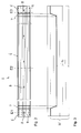
- FIGS. 1 to 4 will be described together below.
- a safety barrier 2 according to the invention for a safety device 3 which are mounted along roadways for motor vehicles and serve for protection if vehicles deviate from the roadway.
- individual guard rails 2 are detachably connected to each other and attached via posts 4 along a roadway.
- FIG. 1 is a single guardrail 2, which may also be referred to as a guardrail, in perspective view and in FIG. 2 shown in side view.
- the protective barrier 2 is made of a steel material by forming.
- the protective barrier 2 comprises at its ends in each case a first section 5 with a first material thickness D5 and an intermediate second section 6 with a second material thickness D6, which is smaller than the material thickness D5 of the end-side first sections.
- a transition section 7 is formed in each case, in which the material thickness steadily decreases starting from the thicker section in the direction of the thinner section.
- the first section 5 extends over a length L5, the second section 6 over a length L6 and the transition section 7 over a length L7.
- the length L7 of the transition section 7 is shorter than the length L5 of the thicker first section 5.
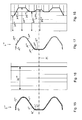
- FIG. 3 showing the thickness profile of the protective barrier 2 over the length, the ratio of the material thickness D6 of the thinner second portion 6 to the material thickness D5 of the thicker portion 5 is about 2 to 3, wherein here other thickness ratios would be conceivable, for example, between 1 to 2 to 4 to 5 can lie. Due to the variable thickness of the protective barrier 2 over the length of the guard rail 2 can be adjusted individually to the requirements in terms of strength or rigidity. It is understood that other thicknesses than the thickness profile shown are conceivable. For example, in addition to or as an alternative to the first sections 5, at the ends of the guardrail 2 are formed, also one or more thicker first portions are provided in the central region of the guardrail.
- the thickness profile of the guardrail is designed approximately wave-shaped, that is, that the material thickness decreases in each case from the thicker first sections, then reaches a minimum and increases again following the minimum towards the next thicker first section.
- the second section would be formed in the region of the minimum and shortened to a minimum length.
- the transition sections would be formed with a continuous change in thickness over the length correspondingly long.
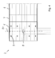
- the protective barrier 2 has distributed over its length a plurality of through holes 8, which are designed in particular in the form of slots. These passage openings 8 are arranged approximately centrally with respect to the width of the protective barrier 2 and serve for attaching the protective barrier 2 to a post 4, which in turn is anchored in the ground. The connection between the guardrail 2 and the post 4 via screw that are not shown here.
- the passage openings 8 are distributed at regular intervals over the length of the protective barrier 2. In each case, only a single first passage opening 8 is located in each cross-sectional plane.
- the material thickness D5 in the thicker first section 5, in which the first passage opening 8 is provided for attachment to the post 4, is in particular designed such that the cross-sectional area in a sectional plane E1 in which the first passage opening 8 is located, is equal to or greater than the cross-sectional area through the guard rail 2 in a plane E2, in which no passage opening is present.
- This embodiment results in a high rigidity or strength of the protective barrier 2 in the connection region, so that it is prevented in the event of an impact that the protective barrier 2 tears and is separated from the post 4 here.
- second through holes 9 are provided at the end portions of the guard rail 2.
- a plurality of second passage openings 9 are arranged distributed over the width of the guardrail 2. These second passage openings 9 serve for fastening two Guard rails 2 together. The attachment is usually done by means of screw. It can be seen that in the present case two rows of second through-openings 9 are provided at each end of the protective barrier 2, of which a first row lies on one side of the first through-opening 8 and a second row lies on the other side of the first through-opening 8.
- the cross-sectional area of the guardrail in a plane E3 in which the second passage openings 9 are arranged be equal to or greater than the cross-sectional area of the guard rail 2 in the plane E2 in which there are no holes or other weakening zones are provided. This results in the second through holes 9 sufficient strength of the guardrail 2, which prevents the guardrail 2 is torn in an impact of a motor vehicle.
- the present embodiment of the guard rail 2 with variable length material thickness is preferably made by flexibly rolling a sheet metal strip. After the flexible rolling, the sheet metal strip is cut to length according to the desired length and the passage openings for fixing the protective barrier 2 to a post 4 or more guard rails 2 are inserted into one another in the sheet metal.
- the contour of the protective barrier 2 is produced by roll profiling or deep drawing.
- a heat treatment can be provided as a further process step. The heat treatment can take place between or after the individual process steps.
- FIGS. 5 to 8 show a protective barrier 2 'according to the invention in a second embodiment. This corresponds in many parts to those according to the FIGS. 1 to 3 , so that reference is made to the above description in terms of similarities.
- the guardrail 2 'across the width has a variable material thickness, as best shown in FIGS FIGS. 7 and 8 can be seen, a section along the line VII-VII in FIG 6, and show the thickness over the width of the guardrail 2 '.
- the guardrail 2 ' is designed mirror-symmetrically with respect to the center plane M, which applies both in relation to the contour and with respect to the thickness profile.
- the protective barrier with respect to the plane M has an asymmetrical configuration of the thickness profile over the width.
- the profile of the guardrail in cross-section considered asymmetrical.
- the protective plank 2 " has a first section 11 with a first material thickness D11, which represents the largest material thickness of the protective plank 2" and can be, for example, 3 mm. Furthermore, a second section 12 with the smallest wall thickness D12 can be seen, which is formed on the outer edge of the protective plank 2 ", which can have, for example, a wall thickness of 2 mm.
- the material thickness in the transition section 13 which has a variable thickness D13 in the transverse direction, increases from the thickness D12 to the thickness D11 of the first section 11.
- the thickness profile of the transition section 13 is continuous.
- the first section 11 has a curved portion, which points in the assembled state in the direction of the roadway, and an adjoining straight portion which extends at an angle in the direction of the center plane.
- a bent section 14 with a significantly reduced thickness D14 follows.
- a transition section 17 with a wall thickness D17 increasing in the direction of the center plane M again adjoins the bent section 14.
- the transition portion 17 is relatively short, in particular shorter than the outer adjacent curved portion 14 or the inner adjoining central portion 16.
- the middle portion 16, which can also be referred to as the fourth section has the thickness D16. This is approximately the same as the largest thickness D11 of the first portion 11. It is understood that the central portion 16 may also have the thickness D11, as the first portion 11.
- the further course of the material thickness results from the symmetry of the protective barrier.
- the sections 11, 16 of greater material thickness alternate with the sections 12, 14 of smaller thickness. In each case, differently extended ramp-like transition sections 13, 15, 17 are arranged.
- the protective barrier 2 'according to the invention according to the present embodiment is preferably produced by means of strip profile rolling of a sheet. With the strip profile rolling, the material thickness of the sheet is changed across the width.
- the band profile rolling can be done before, during or after the roll profiling or deep drawing, with which the contour of the guardrail is generated.
- FIGS. 9 to 13 3 shows a third embodiment of a protective barrier 2 "according to the invention, in which the thickness of the material is varied both over the length and across the width
- the course of the thickness over the length with a middle second section 6 and two edge-side first sections 5 and Interposed transition regions 7 corresponds approximately to that in the FIG. 3 illustrated course.
- the three-dimensional structure of the material thickness over the protective barrier 2 "results from a combination of the thickness profiles according to the Figures 3 and 8th ,
- the present embodiment according to the FIGS. 9 to 13 a combination of the two embodiments mentioned above.
- the present embodiment has the thickest thickness profile across the width in the section 5 ", the corresponding cross section through the section 5" being in FIG FIG. 10 shown.
- the transverse section 11 within the longitudinal section 5 "of the transverse section 11 have a thickest material thickness of 3.0 mm, while the thinnest transverse section 12 may have a material thickness of 2.0.
- the second longitudinal section has the same thickness over the cross section, only at a slightly lower level.
- all sections 12 ', 13', 11 ', 15', 14 ', 17', 16 'of the second longitudinal section 6 have a slightly smaller material thickness D12', D13 ', D11', D15 ', D14', D17 ', D16' as the corresponding sections 12, 13, 11, 15, 14, 17, 16 of the first longitudinal section 5 ".
- the thickness difference may be 0.5 to 1.0 mm, for example.
- a corresponding ramp-like transition takes place between the respectively longitudinally adjacent longitudinal sections 12, 12 ', 13, 13', etc.
- the production of the protective barrier 2 is effected by the combination of the method steps of flexible rolling, by means of which a band with variable wall thickness is produced with thicker first sections 5, transition sections 7 and thinner second sections 6, and strip profile rollers, by means of which subsequently sections 11, 12, 13, 14, 15, 16, 17 are produced over the width of different thickness.
- FIGS. 14 to 18 There is shown a fourth embodiment of a protective barrier 2 '"according to the invention, in which the thickness of the material is varied over both the length and the width FIGS. 9 to 13 so that in terms of the similarities to the above description, and thus to the description of the FIGS. 1 to 8 Reference can be made.
- the course of the thickness over the length with a middle second portion 6 '"and two edge-side first portions 5'" and arranged therebetween transition regions 7 '" corresponds approximately to that in the FIG. 3 illustrated course.
- the variation of the thickness across the width of the guardrail 2 '"in the second section 6'" corresponds to that in the FIG. 8 illustrated course. This is represented by the specification of sections with the thicknesses D11 to D17. The respective sections extend along the guardrail 2 "', over the second section 6"'.
- the present embodiment has the thickest thickness profile across the width in the section 5 " FIG. 10 , which shows a cross-section through the section 5 '", recognizable that the protective barrier 2'" here over the entire width of a constant maximum thickness D5 "'. That is, the individual transverse sections 12", 13 “, 11", 15 “, 14", 17 “and 16” all have the same thickness D5 "', which may be 3.0 mm, for example.
- the guardrail 2 '" has in the second section 6''' the same thickness profile over the cross section, as in the embodiment according to the FIGS. 5 to 8 ,
- a corresponding ramp-like transition takes place between the respectively longitudinally adjacent sections 12", 13 ", etc. of the first longitudinal section 5 '''and the corresponding sections 12'',13'', etc. of the second longitudinal section 6''.
- the production of the protective barrier 2 " is effected by the combination of the method steps flexible rolling, by means of which a band over the length of variable wall thickness with thicker first sections 5, transition sections 7 and thinner second sections 6 is generated, and strip profile rollers, by means of the subsequently in the second longitudinal section
- the sections 11 "', 12"', 13 “', 14"', 15 “', 16"', 17 “'with over the width of different thickness are produced.
- the embodiments shown are only exemplary in terms of the thickness profiles over the length or the width. Of course, other thickness profiles over the length or over the width are conceivable.
- another protective barrier could also be designed such that in the first section 5 it has a profile with a width which is variable over the width, as shown in FIG. 8 is shown, and in the second section 6 has a constant thickness over the width, as in the embodiment according to the FIGS. 1 to 4 , A transition section 7 would connect the thicknesses of the first and second sections accordingly.
- the ratio between the thinner second material thickness and the thicker first material thickness may be between 1/10 and 9/10, preferably between 1/3 and 4/5 or 1/2 and 4/5, and is in particular between 1/3 and 3 / 4, or between 2/3 and 3/4.
- All of the protective barriers according to the invention described above have the advantage that they can be adapted individually with respect to the material thickness over the length or over the width to the requirements in terms of strength or rigidity.
Applications Claiming Priority (1)
| Application Number | Priority Date | Filing Date | Title |
|---|---|---|---|
| DE102010037118A DE102010037118A1 (de) | 2010-08-23 | 2010-08-23 | Schutzplanke für eine Sicherheitseinrichtung an einer Straße und Verfahren zur Herstellung einer Schutzplanke |
Publications (3)
| Publication Number | Publication Date |
|---|---|
| EP2423385A2 true EP2423385A2 (de) | 2012-02-29 |
| EP2423385A3 EP2423385A3 (de) | 2014-10-22 |
| EP2423385B1 EP2423385B1 (de) | 2017-09-20 |
Family
ID=44584061
Family Applications (1)
| Application Number | Title | Priority Date | Filing Date |
|---|---|---|---|
| EP11178357.7A Active EP2423385B1 (de) | 2010-08-23 | 2011-08-22 | Schutzplanke für eine Sicherheitseinrichtung an einer Straße und Verfahren zur Herstellung einer Schutzplanke |
Country Status (2)
| Country | Link |
|---|---|
| EP (1) | EP2423385B1 (pt-PT) |
| DE (1) | DE102010037118A1 (pt-PT) |
Citations (11)
| Publication number | Priority date | Publication date | Assignee | Title |
|---|---|---|---|---|
| CH449689A (de) | 1967-05-19 | 1968-01-15 | Alusuisse | Strassenleitplanke aus Verbundwerkstoff |
| DE1291349B (de) | 1961-05-18 | 1969-03-27 | Alusuisse | Strassenleitplanke |
| DE2010127A1 (de) | 1970-03-04 | 1971-09-23 | Weisbender, Helmut, 5430 Montabaur | Leitplanke |
| GB1272588A (en) | 1968-09-04 | 1972-05-03 | British Ropes Ltd | Improvements in or relating to vehicle retention barriers |
| EP0246545A2 (en) | 1986-05-20 | 1987-11-25 | Carbone Magni, Magda | Movable-element guard-rail |
| DE10041280A1 (de) | 2000-08-22 | 2002-03-21 | Muhr & Bender Kg | Verfahren und Vorrichtung zum flexiblen Walzen eines Metallbandes |
| DE202004013606U1 (de) | 2004-08-30 | 2004-10-28 | SGGT Straßenausstattungen GmbH | Passive Schutzeinrichtung neben einer Fahrbahn einer Kraftfahrzeugstraße |
| EP1555349A1 (en) | 2004-01-14 | 2005-07-20 | SNOLINE S.p.A. | Motorcyclist protective barrier |
| DE102004034999A1 (de) | 2004-03-10 | 2005-10-13 | TOGE-Dübel A. Gerhard KG | Leitplanken-Pfosten |
| DE102005039705A1 (de) | 2005-05-10 | 2006-11-16 | Durabel Baubedarf Gmbh | Verkehrs-Leit-Einrichtung |
| DE102009056514A1 (de) | 2009-12-02 | 2010-08-19 | Dreistern Gmbh & Co. Kg | Walzverfahren und Walzvorrichtung zum Herstellen eines Metallbandes mit einer über seine Breite variierenden Dicke |
Family Cites Families (3)
| Publication number | Priority date | Publication date | Assignee | Title |
|---|---|---|---|---|
| DE3816528A1 (de) * | 1987-09-10 | 1989-03-23 | Spig Schutzplanken Prod Gmbh | Fahrwegseitenbegrenzung |
| US7794174B2 (en) * | 2007-01-29 | 2010-09-14 | Traffix Devices, Inc. | Crash impact attenuator systems and methods |
| DE102008017939B3 (de) * | 2008-04-08 | 2009-07-16 | Spig Schutzplanken-Produktions-Gesellschaft Mbh & Co. Kg | Fahrzeugrückhaltesystem |
-
2010
- 2010-08-23 DE DE102010037118A patent/DE102010037118A1/de not_active Withdrawn
-
2011
- 2011-08-22 EP EP11178357.7A patent/EP2423385B1/de active Active
Patent Citations (11)
| Publication number | Priority date | Publication date | Assignee | Title |
|---|---|---|---|---|
| DE1291349B (de) | 1961-05-18 | 1969-03-27 | Alusuisse | Strassenleitplanke |
| CH449689A (de) | 1967-05-19 | 1968-01-15 | Alusuisse | Strassenleitplanke aus Verbundwerkstoff |
| GB1272588A (en) | 1968-09-04 | 1972-05-03 | British Ropes Ltd | Improvements in or relating to vehicle retention barriers |
| DE2010127A1 (de) | 1970-03-04 | 1971-09-23 | Weisbender, Helmut, 5430 Montabaur | Leitplanke |
| EP0246545A2 (en) | 1986-05-20 | 1987-11-25 | Carbone Magni, Magda | Movable-element guard-rail |
| DE10041280A1 (de) | 2000-08-22 | 2002-03-21 | Muhr & Bender Kg | Verfahren und Vorrichtung zum flexiblen Walzen eines Metallbandes |
| EP1555349A1 (en) | 2004-01-14 | 2005-07-20 | SNOLINE S.p.A. | Motorcyclist protective barrier |
| DE102004034999A1 (de) | 2004-03-10 | 2005-10-13 | TOGE-Dübel A. Gerhard KG | Leitplanken-Pfosten |
| DE202004013606U1 (de) | 2004-08-30 | 2004-10-28 | SGGT Straßenausstattungen GmbH | Passive Schutzeinrichtung neben einer Fahrbahn einer Kraftfahrzeugstraße |
| DE102005039705A1 (de) | 2005-05-10 | 2006-11-16 | Durabel Baubedarf Gmbh | Verkehrs-Leit-Einrichtung |
| DE102009056514A1 (de) | 2009-12-02 | 2010-08-19 | Dreistern Gmbh & Co. Kg | Walzverfahren und Walzvorrichtung zum Herstellen eines Metallbandes mit einer über seine Breite variierenden Dicke |
Also Published As
| Publication number | Publication date |
|---|---|
| EP2423385A3 (de) | 2014-10-22 |
| DE102010037118A1 (de) | 2012-02-23 |
| EP2423385B1 (de) | 2017-09-20 |
Similar Documents
| Publication | Publication Date | Title |
|---|---|---|
| DE102011051622B4 (de) | Verstärkungselement für eine Fahrzeugstruktur, insbesondere für einen Schweller eines Kraftfahrzeugs | |
| DE102013114690B4 (de) | Außenpaneel für eine Fahrzeugsäule | |
| DE2304147A1 (de) | Stossdaempfer insbesondere fuer leitschienenanordnungen | |
| DE4224998C1 (en) | Protective crash barrier for highways - comprises posts anchored in ground, deformation profile on road side, upper and lower longitudinal rails | |
| EP0874940B1 (de) | Schutzplankenanordnung | |
| EP1719840A2 (de) | Schutzplankenanordnung | |
| WO2012110208A1 (de) | STOßFÄNGER FÜR KRAFTFAHRZEUGE MIT INTEGRIERTERN FUßGÄNGERSCHUTZSYSTEM | |
| WO2018060143A1 (de) | Strukturbauteil für eine kraftfahrzeugkarosserie | |
| EP1630295B1 (de) | Passive Schutzeinrichtung neben einer Fahrbahn einer Kraftfahrzeugstrasse | |
| EP1908882A1 (de) | Schutzplankenanordnung | |
| DE102008017939B3 (de) | Fahrzeugrückhaltesystem | |
| EP3795751B1 (de) | Anpralldämpfer und schutzeinrichtung an objekten | |
| EP3901006A1 (de) | Kraftfahrzeugbauteil | |
| EP2423385B1 (de) | Schutzplanke für eine Sicherheitseinrichtung an einer Straße und Verfahren zur Herstellung einer Schutzplanke | |
| DE4017455A1 (de) | Doppelleitplanke zur sicherung von strassen | |
| DE19536915C2 (de) | Schutzplankenanordnung | |
| DE102011055960A1 (de) | Fahrzeugrückhaltesystem | |
| EP1876300B1 (de) | Schutzplankenstrang aus Stahl | |
| EP1486615A1 (de) | Schutzplankenstrang | |
| EP2520719B1 (de) | Fahrzeugrückhaltesystem mit Anprallmatten | |
| DE102012106249B4 (de) | Stoßfängerprofil | |
| DE10108352B4 (de) | Strukturbauelement für den Fahrzeugbau | |
| DE102022129907B3 (de) | Bodenstruktur für eine Karosserie eines elektrisch antreibbaren Kraftwagens | |
| DE102018130460B4 (de) | Stoßfängeranordnung für ein Kraftfahrzeug | |
| DE102016124690A1 (de) | Seitenaufprallträger für ein Kraftfahrzeug |
Legal Events
| Date | Code | Title | Description |
|---|---|---|---|
| AK | Designated contracting states |
Kind code of ref document: A2 Designated state(s): AL AT BE BG CH CY CZ DE DK EE ES FI FR GB GR HR HU IE IS IT LI LT LU LV MC MK MT NL NO PL PT RO RS SE SI SK SM TR |
|
| AX | Request for extension of the european patent |
Extension state: BA ME |
|
| PUAI | Public reference made under article 153(3) epc to a published international application that has entered the european phase |
Free format text: ORIGINAL CODE: 0009012 |
|
| PUAL | Search report despatched |
Free format text: ORIGINAL CODE: 0009013 |
|
| AK | Designated contracting states |
Kind code of ref document: A3 Designated state(s): AL AT BE BG CH CY CZ DE DK EE ES FI FR GB GR HR HU IE IS IT LI LT LU LV MC MK MT NL NO PL PT RO RS SE SI SK SM TR |
|
| AX | Request for extension of the european patent |
Extension state: BA ME |
|
| RIC1 | Information provided on ipc code assigned before grant |
Ipc: E01F 15/04 20060101AFI20140917BHEP |
|
| 17P | Request for examination filed |
Effective date: 20141217 |
|
| RBV | Designated contracting states (corrected) |
Designated state(s): AL AT BE BG CH CY CZ DE DK EE ES FI FR GB GR HR HU IE IS IT LI LT LU LV MC MK MT NL NO PL PT RO RS SE SI SK SM TR |
|
| STAA | Information on the status of an ep patent application or granted ep patent |
Free format text: STATUS: EXAMINATION IS IN PROGRESS |
|
| 17Q | First examination report despatched |
Effective date: 20161024 |
|
| GRAP | Despatch of communication of intention to grant a patent |
Free format text: ORIGINAL CODE: EPIDOSNIGR1 |
|
| STAA | Information on the status of an ep patent application or granted ep patent |
Free format text: STATUS: GRANT OF PATENT IS INTENDED |
|
| INTG | Intention to grant announced |
Effective date: 20170320 |
|
| GRAS | Grant fee paid |
Free format text: ORIGINAL CODE: EPIDOSNIGR3 |
|
| GRAA | (expected) grant |
Free format text: ORIGINAL CODE: 0009210 |
|
| STAA | Information on the status of an ep patent application or granted ep patent |
Free format text: STATUS: THE PATENT HAS BEEN GRANTED |
|
| RAP1 | Party data changed (applicant data changed or rights of an application transferred) |
Owner name: MUHR UND BENDER KG |
|
| AK | Designated contracting states |
Kind code of ref document: B1 Designated state(s): AL AT BE BG CH CY CZ DE DK EE ES FI FR GB GR HR HU IE IS IT LI LT LU LV MC MK MT NL NO PL PT RO RS SE SI SK SM TR |
|
| REG | Reference to a national code |
Ref country code: GB Ref legal event code: FG4D Free format text: NOT ENGLISH |
|
| REG | Reference to a national code |
Ref country code: CH Ref legal event code: EP |
|
| REG | Reference to a national code |
Ref country code: AT Ref legal event code: REF Ref document number: 930204 Country of ref document: AT Kind code of ref document: T Effective date: 20171015 |
|
| REG | Reference to a national code |
Ref country code: IE Ref legal event code: FG4D Free format text: LANGUAGE OF EP DOCUMENT: GERMAN |
|
| REG | Reference to a national code |
Ref country code: DE Ref legal event code: R096 Ref document number: 502011013013 Country of ref document: DE |
|
| REG | Reference to a national code |
Ref country code: NL Ref legal event code: MP Effective date: 20170920 |
|
| PG25 | Lapsed in a contracting state [announced via postgrant information from national office to epo] |
Ref country code: LT Free format text: LAPSE BECAUSE OF FAILURE TO SUBMIT A TRANSLATION OF THE DESCRIPTION OR TO PAY THE FEE WITHIN THE PRESCRIBED TIME-LIMIT Effective date: 20170920 Ref country code: FI Free format text: LAPSE BECAUSE OF FAILURE TO SUBMIT A TRANSLATION OF THE DESCRIPTION OR TO PAY THE FEE WITHIN THE PRESCRIBED TIME-LIMIT Effective date: 20170920 Ref country code: HR Free format text: LAPSE BECAUSE OF FAILURE TO SUBMIT A TRANSLATION OF THE DESCRIPTION OR TO PAY THE FEE WITHIN THE PRESCRIBED TIME-LIMIT Effective date: 20170920 Ref country code: NO Free format text: LAPSE BECAUSE OF FAILURE TO SUBMIT A TRANSLATION OF THE DESCRIPTION OR TO PAY THE FEE WITHIN THE PRESCRIBED TIME-LIMIT Effective date: 20171220 Ref country code: SE Free format text: LAPSE BECAUSE OF FAILURE TO SUBMIT A TRANSLATION OF THE DESCRIPTION OR TO PAY THE FEE WITHIN THE PRESCRIBED TIME-LIMIT Effective date: 20170920 |
|
| REG | Reference to a national code |
Ref country code: LT Ref legal event code: MG4D |
|
| PG25 | Lapsed in a contracting state [announced via postgrant information from national office to epo] |
Ref country code: GR Free format text: LAPSE BECAUSE OF FAILURE TO SUBMIT A TRANSLATION OF THE DESCRIPTION OR TO PAY THE FEE WITHIN THE PRESCRIBED TIME-LIMIT Effective date: 20171221 Ref country code: RS Free format text: LAPSE BECAUSE OF FAILURE TO SUBMIT A TRANSLATION OF THE DESCRIPTION OR TO PAY THE FEE WITHIN THE PRESCRIBED TIME-LIMIT Effective date: 20170920 Ref country code: LV Free format text: LAPSE BECAUSE OF FAILURE TO SUBMIT A TRANSLATION OF THE DESCRIPTION OR TO PAY THE FEE WITHIN THE PRESCRIBED TIME-LIMIT Effective date: 20170920 Ref country code: BG Free format text: LAPSE BECAUSE OF FAILURE TO SUBMIT A TRANSLATION OF THE DESCRIPTION OR TO PAY THE FEE WITHIN THE PRESCRIBED TIME-LIMIT Effective date: 20171220 |
|
| PG25 | Lapsed in a contracting state [announced via postgrant information from national office to epo] |
Ref country code: NL Free format text: LAPSE BECAUSE OF FAILURE TO SUBMIT A TRANSLATION OF THE DESCRIPTION OR TO PAY THE FEE WITHIN THE PRESCRIBED TIME-LIMIT Effective date: 20170920 |
|
| PG25 | Lapsed in a contracting state [announced via postgrant information from national office to epo] |
Ref country code: RO Free format text: LAPSE BECAUSE OF FAILURE TO SUBMIT A TRANSLATION OF THE DESCRIPTION OR TO PAY THE FEE WITHIN THE PRESCRIBED TIME-LIMIT Effective date: 20170920 Ref country code: CZ Free format text: LAPSE BECAUSE OF FAILURE TO SUBMIT A TRANSLATION OF THE DESCRIPTION OR TO PAY THE FEE WITHIN THE PRESCRIBED TIME-LIMIT Effective date: 20170920 Ref country code: ES Free format text: LAPSE BECAUSE OF FAILURE TO SUBMIT A TRANSLATION OF THE DESCRIPTION OR TO PAY THE FEE WITHIN THE PRESCRIBED TIME-LIMIT Effective date: 20170920 Ref country code: PL Free format text: LAPSE BECAUSE OF FAILURE TO SUBMIT A TRANSLATION OF THE DESCRIPTION OR TO PAY THE FEE WITHIN THE PRESCRIBED TIME-LIMIT Effective date: 20170920 |
|
| PG25 | Lapsed in a contracting state [announced via postgrant information from national office to epo] |
Ref country code: SM Free format text: LAPSE BECAUSE OF FAILURE TO SUBMIT A TRANSLATION OF THE DESCRIPTION OR TO PAY THE FEE WITHIN THE PRESCRIBED TIME-LIMIT Effective date: 20170920 Ref country code: SK Free format text: LAPSE BECAUSE OF FAILURE TO SUBMIT A TRANSLATION OF THE DESCRIPTION OR TO PAY THE FEE WITHIN THE PRESCRIBED TIME-LIMIT Effective date: 20170920 Ref country code: EE Free format text: LAPSE BECAUSE OF FAILURE TO SUBMIT A TRANSLATION OF THE DESCRIPTION OR TO PAY THE FEE WITHIN THE PRESCRIBED TIME-LIMIT Effective date: 20170920 Ref country code: IT Free format text: LAPSE BECAUSE OF FAILURE TO SUBMIT A TRANSLATION OF THE DESCRIPTION OR TO PAY THE FEE WITHIN THE PRESCRIBED TIME-LIMIT Effective date: 20170920 Ref country code: IS Free format text: LAPSE BECAUSE OF FAILURE TO SUBMIT A TRANSLATION OF THE DESCRIPTION OR TO PAY THE FEE WITHIN THE PRESCRIBED TIME-LIMIT Effective date: 20180120 |
|
| REG | Reference to a national code |
Ref country code: DE Ref legal event code: R097 Ref document number: 502011013013 Country of ref document: DE |
|
| PLBE | No opposition filed within time limit |
Free format text: ORIGINAL CODE: 0009261 |
|
| STAA | Information on the status of an ep patent application or granted ep patent |
Free format text: STATUS: NO OPPOSITION FILED WITHIN TIME LIMIT |
|
| PG25 | Lapsed in a contracting state [announced via postgrant information from national office to epo] |
Ref country code: DK Free format text: LAPSE BECAUSE OF FAILURE TO SUBMIT A TRANSLATION OF THE DESCRIPTION OR TO PAY THE FEE WITHIN THE PRESCRIBED TIME-LIMIT Effective date: 20170920 |
|
| 26N | No opposition filed |
Effective date: 20180621 |
|
| PG25 | Lapsed in a contracting state [announced via postgrant information from national office to epo] |
Ref country code: MT Free format text: LAPSE BECAUSE OF FAILURE TO SUBMIT A TRANSLATION OF THE DESCRIPTION OR TO PAY THE FEE WITHIN THE PRESCRIBED TIME-LIMIT Effective date: 20170920 |
|
| PG25 | Lapsed in a contracting state [announced via postgrant information from national office to epo] |
Ref country code: SI Free format text: LAPSE BECAUSE OF FAILURE TO SUBMIT A TRANSLATION OF THE DESCRIPTION OR TO PAY THE FEE WITHIN THE PRESCRIBED TIME-LIMIT Effective date: 20170920 |
|
| PG25 | Lapsed in a contracting state [announced via postgrant information from national office to epo] |
Ref country code: MC Free format text: LAPSE BECAUSE OF FAILURE TO SUBMIT A TRANSLATION OF THE DESCRIPTION OR TO PAY THE FEE WITHIN THE PRESCRIBED TIME-LIMIT Effective date: 20170920 |
|
| REG | Reference to a national code |
Ref country code: CH Ref legal event code: PL |
|
| GBPC | Gb: european patent ceased through non-payment of renewal fee |
Effective date: 20180822 |
|
| PG25 | Lapsed in a contracting state [announced via postgrant information from national office to epo] |
Ref country code: LU Free format text: LAPSE BECAUSE OF NON-PAYMENT OF DUE FEES Effective date: 20180822 Ref country code: LI Free format text: LAPSE BECAUSE OF NON-PAYMENT OF DUE FEES Effective date: 20180831 Ref country code: CH Free format text: LAPSE BECAUSE OF NON-PAYMENT OF DUE FEES Effective date: 20180831 |
|
| REG | Reference to a national code |
Ref country code: BE Ref legal event code: MM Effective date: 20180831 |
|
| PG25 | Lapsed in a contracting state [announced via postgrant information from national office to epo] |
Ref country code: FR Free format text: LAPSE BECAUSE OF NON-PAYMENT OF DUE FEES Effective date: 20180831 Ref country code: BE Free format text: LAPSE BECAUSE OF NON-PAYMENT OF DUE FEES Effective date: 20180831 |
|
| REG | Reference to a national code |
Ref country code: AT Ref legal event code: MM01 Ref document number: 930204 Country of ref document: AT Kind code of ref document: T Effective date: 20180822 |
|
| PG25 | Lapsed in a contracting state [announced via postgrant information from national office to epo] |
Ref country code: GB Free format text: LAPSE BECAUSE OF NON-PAYMENT OF DUE FEES Effective date: 20180822 |
|
| PG25 | Lapsed in a contracting state [announced via postgrant information from national office to epo] |
Ref country code: AT Free format text: LAPSE BECAUSE OF NON-PAYMENT OF DUE FEES Effective date: 20180822 |
|
| PG25 | Lapsed in a contracting state [announced via postgrant information from national office to epo] |
Ref country code: TR Free format text: LAPSE BECAUSE OF FAILURE TO SUBMIT A TRANSLATION OF THE DESCRIPTION OR TO PAY THE FEE WITHIN THE PRESCRIBED TIME-LIMIT Effective date: 20170920 |
|
| PG25 | Lapsed in a contracting state [announced via postgrant information from national office to epo] |
Ref country code: PT Free format text: LAPSE BECAUSE OF FAILURE TO SUBMIT A TRANSLATION OF THE DESCRIPTION OR TO PAY THE FEE WITHIN THE PRESCRIBED TIME-LIMIT Effective date: 20170920 Ref country code: HU Free format text: LAPSE BECAUSE OF FAILURE TO SUBMIT A TRANSLATION OF THE DESCRIPTION OR TO PAY THE FEE WITHIN THE PRESCRIBED TIME-LIMIT; INVALID AB INITIO Effective date: 20110822 |
|
| PG25 | Lapsed in a contracting state [announced via postgrant information from national office to epo] |
Ref country code: MK Free format text: LAPSE BECAUSE OF NON-PAYMENT OF DUE FEES Effective date: 20170920 Ref country code: CY Free format text: LAPSE BECAUSE OF FAILURE TO SUBMIT A TRANSLATION OF THE DESCRIPTION OR TO PAY THE FEE WITHIN THE PRESCRIBED TIME-LIMIT Effective date: 20170920 Ref country code: IE Free format text: LAPSE BECAUSE OF NON-PAYMENT OF DUE FEES Effective date: 20180822 |
|
| PG25 | Lapsed in a contracting state [announced via postgrant information from national office to epo] |
Ref country code: AL Free format text: LAPSE BECAUSE OF FAILURE TO SUBMIT A TRANSLATION OF THE DESCRIPTION OR TO PAY THE FEE WITHIN THE PRESCRIBED TIME-LIMIT Effective date: 20170920 |
|
| PGFP | Annual fee paid to national office [announced via postgrant information from national office to epo] |
Ref country code: DE Payment date: 20230731 Year of fee payment: 13 |