EP2602601A1 - Überwachungssystem einer kinematischen Kette - Google Patents
Überwachungssystem einer kinematischen Kette Download PDFInfo
- Publication number
- EP2602601A1 EP2602601A1 EP20120193457 EP12193457A EP2602601A1 EP 2602601 A1 EP2602601 A1 EP 2602601A1 EP 20120193457 EP20120193457 EP 20120193457 EP 12193457 A EP12193457 A EP 12193457A EP 2602601 A1 EP2602601 A1 EP 2602601A1
- Authority
- EP
- European Patent Office
- Prior art keywords
- primary
- shaft
- monitoring
- rotation
- kinematic chain
- Prior art date
- Legal status (The legal status is an assumption and is not a legal conclusion. Google has not performed a legal analysis and makes no representation as to the accuracy of the status listed.)
- Granted
Links
- 238000012544 monitoring process Methods 0.000 title claims abstract description 103
- 230000007257 malfunction Effects 0.000 claims abstract description 24
- 230000005540 biological transmission Effects 0.000 claims abstract description 23
- 238000000034 method Methods 0.000 claims abstract description 12
- 230000033001 locomotion Effects 0.000 claims description 19
- 230000003068 static effect Effects 0.000 claims description 14
- 230000008569 process Effects 0.000 claims description 2
- 238000010586 diagram Methods 0.000 description 8
- 238000001514 detection method Methods 0.000 description 7
- 238000006073 displacement reaction Methods 0.000 description 4
- 241001417494 Sciaenidae Species 0.000 description 3
- 230000004044 response Effects 0.000 description 3
- 230000008859 change Effects 0.000 description 2
- 230000008878 coupling Effects 0.000 description 2
- 238000010168 coupling process Methods 0.000 description 2
- 238000005859 coupling reaction Methods 0.000 description 2
- 241000233866 Fungi Species 0.000 description 1
- 230000004913 activation Effects 0.000 description 1
- 230000006978 adaptation Effects 0.000 description 1
- 230000032683 aging Effects 0.000 description 1
- 230000001174 ascending effect Effects 0.000 description 1
- 238000012550 audit Methods 0.000 description 1
- 239000004020 conductor Substances 0.000 description 1
- 230000007547 defect Effects 0.000 description 1
- 230000003287 optical effect Effects 0.000 description 1
- 238000012545 processing Methods 0.000 description 1
- 238000012549 training Methods 0.000 description 1
- 238000012795 verification Methods 0.000 description 1
Images


Classifications
-
- G—PHYSICS
- G01—MEASURING; TESTING
- G01M—TESTING STATIC OR DYNAMIC BALANCE OF MACHINES OR STRUCTURES; TESTING OF STRUCTURES OR APPARATUS, NOT OTHERWISE PROVIDED FOR
- G01M13/00—Testing of machine parts
- G01M13/02—Gearings; Transmission mechanisms
- G01M13/021—Gearings
Definitions
- the present invention relates to kinematic chain monitoring systems. More particularly, this type of system can be used for example to secure winches for handling loads.
- the present invention aims to provide at least in part a solution to the aforementioned problems.
- said system can control in a controlled time a trip output in case of malfunction of kinematic chain.
- said system due to its redundancy, still allows to quickly activate a trip output in case of malfunction of the driveline.
- a malfunction of the kinematic chain is declared in the event of exceeding at least a predetermined speed threshold on the primary or secondary shaft, and / or in case of desynchronism of the positions between the primary shaft and the secondary tree; so a fault in overspeed or desynchronism causes the kinematic chain of the kinematic chain to be put in a safe state.
- the transmission has a transmission ratio noted K, the angular position of the primary shaft is denoted ⁇ 1, the angular position of the secondary shaft is denoted ⁇ 2, and a desynchronism is detected if the absolute value of ⁇ 2 -K. ⁇ 1 exceeds a predetermined value.
- the first and second control units are able to acquire movement orders relating to a drive control of the primary shaft, so that a malfunction of the kinematic chain is declared in case of static deviation ( movement with no order), and / or dynamic deviation (movement direction incoherent with the movement order).
- the predetermined operating criteria are based on at least one parameter table representing characteristics of the kinematic chain, said parameter table being able to be loaded by a user, preferably an informed user, in the first and second monitoring units.
- the monitoring system can be adapted to the specific characteristics of the kinematic chain to be monitored in order to detect in a controlled time and without uncertainty a malfunction of the kinematic chain.
- the monitoring system may further comprise a third sensor capable of delivering another of the first signals representative of the speed and direction of rotation of the primary shaft and read by the second monitoring unit, and a fourth sensor capable of delivering another of the second signals representative of the speed and direction of rotation of the secondary shaft, and read by the first monitoring unit, so that a failure of one of the sensors does not degrade the function of system monitoring and machine availability.
- the first and second sensors are of the pulse encoder type for measuring the speed and detecting the direction of rotation.
- the monitoring system uses non-specific capture components and the cost of the monitoring system is moderate.
- a plurality of overspeed thresholds may be defined to determine an overspeed condition; so that we can have several levels of protection.
- the brake device can be actuated in the safety position in the event of a malfunction declared on the power train, in particular to prevent any drop in the load to be lifted or any damage.
- the brake device is a brake with no current, so that the load is stopped in the absence of energy input to the brake device.
- the brake device comprises a first brake adapted to act on a first brake member connected to the secondary shaft and a second brake adapted to act on a second brake member connected to the primary shaft, the third output being able to simultaneously control the first brake and the second brake.
- a malfunction of the kinematic chain can be declared when exceeding at least a predetermined speed threshold on the primary or secondary shaft, and / or in case of desynchronism of the positions between the primary shaft and the secondary shaft. For which a defect of overspeed or desynchronism causes putting the driveline in a safe state.
- the first and second control units may be able to acquire movement orders relating to a drive control of the input shaft, so that a malfunction of the kinematic chain is declared in the event of static unstacking. , and / or dynamic unwinding.
- several overspeed thresholds may be defined to determine an overspeed condition; so that we can have several levels of protection.
- the kinematic chain comprises a support 90, a primary shaft 11 pivotally mounted on the support about a first axis X, and a secondary shaft 12 pivotally mounted on the support about a second axis Y.
- the axes X and Y are parallel but they could be arranged differently, for example perpendicular to each other.
- the primary and secondary shafts are mounted on the support 90 preferably by means of bearings.
- the support 90 may be for example a closed housing, a structural housing, a base or any other body having the support function.
- the primary shaft 11 can also be considered as the input shaft of the kinematic chain and the secondary shaft 12 is then considered as the output shaft of the kinematic chain.
- the kinematic chain further comprises a transmission 2 which connects the primary shaft 11 to the secondary shaft 12.
- This transmission may comprise one or more gear train (s), and may optionally also include an elastic coupling or clutch .
- the gear train (s) may be parallel type gears, conical or planetary.
- the elastic coupling if it is present, makes it possible to take rapid or sudden changes in the angular velocity of one of the trees.
- the transmission has a transmission ratio denoted K, ratio between the output speed (secondary shaft) and the input speed (primary shaft).
- the surveillance system also includes less a first sensor 21 capable of delivering at least a first signal 41 representative of the speed and direction of rotation of the primary shaft 11.
- the monitoring system comprises at least one second sensor 22 capable of delivering at least one second signal 42 representative of the speed and the direction of rotation of the secondary shaft 12.
- These first and second sensors 21,22 are preferably of the pulse encoder type (also called 'incremental encoder').
- the pulse encoder type also called 'incremental encoder'
- This type of incremental encoder delivers pulses whose frequency is proportional to the speed of displacement of the rotating shaft.
- Each sensor may comprise two rows of pins, for example magnetic or optical, for example several tens of markers per revolution, which makes it possible to deliver signals comprising a large number of pulses per revolution. This type of sensor is relatively common, reliable
- the monitoring system 1 further comprises a first monitoring unit 31 able to acquire said first and second signals 41,42.
- the first monitoring unit 31 can then calculate the angular position of each of the primary and secondary shafts by counting the received pulses.
- the first monitoring unit 31 can compare the positions and rotational speeds of the primary and secondary shafts 11, 12 with respect to predetermined performance criteria which will be explained later.
- the first monitoring unit 31 can then control at least a first output 51 in response to a malfunction if the operating criteria are not met.
- the monitoring system controls the first output 51 in a state which corresponds to a state of security of the system, also called 'security status' thereafter.
- the first output 51 will be controlled in a state called “activated” if the predetermined operating criteria are met and will be controlled in an inactive state in case of detection of a malfunction.
- a supply of control energy will allow the operation or displacement and an absence of control energy will oppose the displacement.
- the monitoring system comprises a second monitoring unit 32, similar to the first, able to acquire the first and second signals 41,42. By reading these signals, the second monitoring unit 32 can then calculate on its side the angular positions of the primary and secondary shafts by counting the pulses received, similar to what has been described for the first monitoring unit ci. -above.
- the second monitoring unit 32 can then compare the positions and speeds of rotation of the primary and secondary shafts with respect to the predetermined performance criteria already mentioned above.
- the second monitoring unit 32 can then control at least a second output 52 in a state of safety if the performance criteria are not respected, similar to the first unit 31.
- the first and second monitoring units 31, 32 may be programmable controllers or more specialized monitors. We can choose as an example model 'Motrona' MS640.
- the first and second sensors 21, 22 are connected to the monitoring units by conductors 67 and 68 (cf. Fig. 1 ) respectively according to the connection diagram of the figure 2 .
- the monitoring system comprises an output circuit 33 capable of acquiring said first and second outputs 51, 52.
- the output circuit 33 controls at least a third output 53 in a safe state if at least one of the first and second outputs 51, 52 is in a safe state.
- This third output 53 will be for example a so-called 'dry contact' output isolated from the rest of the circuit, the contact being open, the third output 53 is in a state of security.
- the monitoring system may also comprise the taking into account of several orders of movements 25,26,27 relating to a drive control of the input shaft. Representative inputs of said movement orders 25,26,27 are acquired by the first and second monitoring units 31,32. Thus each of the first and second monitoring units 31,32 is aware of a rotation order in one direction or the other (Ctrl1 Ctrl2) on the primary shaft 11.
- each of the first and second monitoring units 31, 32 may be aware of a high speed command (Ctrl3).
- the predetermined performance criteria may include the verification of the direction of rotation and the adaptation of speed thresholds not to be exceeded, as will be specified below.
- the operating criteria may, for example, include the criteria or conditions that are described below with regard to the corresponding potential malfunctions.
- a first speed threshold (indicated by 65 for V1 and 66 for V2) can correspond for example to the maximum speed expected in low speed operation of the kinematic chain (for example Ctrl3 not active).
- a second speed threshold (indicated by 63 for V1 and 64 for V2) can correspond, for example, to the maximum speed expected during high speed operation of the kinematic chain (for example active Ctrl3).
- the thresholds are of opposite sign in the two directions of rotation, namely V1 and V2 positive or V1 and V2 negative.
- the monitoring units 31,32 control their respective outputs 51,52 and the output circuit 33 controls its output (the third output 53) in a state of security.
- a downstream device connected to this third output for example a brake or a safety system in general then causes the safety of the kinematic chain. It should be noted that it suffices that only one of the monitoring units 31,32 control its output to lead to this result.
- the desynchronism condition is declared by the monitoring units 31,32 which control their respective outputs 51,52.
- the output circuit 33 controls its output (the third output 53) in a safe state.
- the downstream device then causes the setting safety of the kinematic chain as in the previous case. It should be noted that it suffices that only one of the monitoring units 31,32 control its output to lead to this result.
- the normal operating zone 82 is delimited on each side, positive and negative, by the threshold value 81 already mentioned. It can also be said that the desynchronism condition is reached when the absolute value of ⁇ 2-K. ⁇ 1 exceeds the predetermined value 81.
- the condition of static deviation means that the secondary shaft 12 starts to rotate in the absence of rotation control on the primary shaft 11. It will therefore be checked among the criteria of good operation the absence of static deviation.
- Such an unexpected rotation may occur just after the interruption of a move order or permanently.
- the upper curve represents the movement control in a first direction
- the middle curve represents the movement control in the opposite direction
- the bottom curve represents the rotation speed of the secondary shaft 12.
- the chronogram part identified 45 corresponds to a normal operating phase, with a control duration 94 (from T1 to T2) in the first direction, then a stop of the command, a pause 95 (from T2 to T3), then a control duration 96 ( from T3 to T4) in the opposite direction, then a stop of the command.
- a delay 97 takes into account the time necessary for the speed V2 to return to 0. When said time delay has elapsed, then the monitoring of the static deviation is operational.
- the chronogram portion marked 46 corresponds to an operating phase illustrating the detection of static deviation.
- the speed V2 is not zero (marked point 91a), and therefore the static unwinding condition is declared by the monitoring units 31, 32 which then control their respective outputs. 51,52 in the state of safety.
- the dynamic unwinding condition means that the secondary shaft 12 starts to rotate in a direction opposite to the rotational control direction on the primary shaft 11. It will therefore be checked among the criteria of good operation the absence of dynamic unwinding.
- the identified chronogram portion 47 corresponds to an operating phase illustrating the dynamic deviation detection.
- the monitoring units 31, 32 use the speeds V1, V2 but also the positions ⁇ 1, ⁇ 2.
- the monitoring system may furthermore comprise a third sensor 23 in redundancy with the first sensor 21 and a fourth sensor 24 in redundancy with the second sensor 22.
- This third sensor 23 is able to deliver a signal 43 representative of the speed and direction of rotation of the primary shaft, forming a redundant signal of the first signal 41 representative of the speed and direction of rotation of the primary shaft and which is read by the second monitoring unit 32.
- the signals 41, 43 thus form first signals representative of the speed and direction of rotation of the primary shaft 11.
- the fourth sensor 24 is able to deliver a signal 44 representative of the speed and direction of rotation of the secondary shaft, forming a redundant signal of the second signal 42 representative of the speed and direction of rotation of the secondary shaft and which is read by the first monitoring unit 31.
- the signals 42, 44 thus form second signals representative of the speed and the direction of rotation of the secondary shaft 12.
- a winch system for handling loads, adapted to lift a load 16 by means of a cable 15.
- One end of the cable is attached to the load 16 to be lifted, while the other end of the cable is connected to the drum 5 on which can wind a portion of the cable.
- the winch system comprises a kinematic chain as described above, in particular a support 90 constituting the frame of the winch system, a primary shaft 11 (here called a 'fast' shaft) pivoting about an axis X, a secondary shaft 12 (here called a 'slow' shaft) pivoting about a Y axis , the aforementioned drum 5 being attached to the secondary shaft 12.
- a primary shaft 11 here called a 'fast' shaft
- a secondary shaft 12 here called a 'slow' shaft
- the winch system comprises at least one brake device 61, 62 able to act on at least one brake member 71, 72 linked to the primary shaft 11 or to the secondary shaft 12.
- the brake device in question comprises a first brake device 61 adapted to act on a first brake member 71 connected to the drum and secured to the rotating drum, said first brake member 71 here being a brake disc as known in the art.
- a drive device mounted on the support 90, is provided for driving the primary shaft 11 in rotation.
- This drive device comprises a motor unit 4 , preferably of the asynchronous electric motor type.
- the (fast) primary shaft 11 may comprise a second brake member 72, in the example shown in the form of a brake disk.
- a second brake device 62 is arranged in vis-à-vis the second brake member 72 and is able to act on it.
- the first brake device 61 may be a movable jaw caliper provided with friction plates.
- the displacement of the jaws is preferably electrically controlled, although a hydraulic or other control can be equally well envisaged.
- the jaws clamp the disc vis-à-vis when a low or zero control current is applied, which is called in the trade a brake power failure.
- a second training device comprising a transmission 2B in which case it is called 'closed system'.
- a second engine 4B may also be if necessary.
- the Figure 7 illustrates a diagram of the monitoring system 1 implemented in the winch system illustrated on the figure 6 .
- the diagram presented is similar to that of the figure 2 Common elements will not be described again.
- a control circuit 3 acquires the movement commands 25,26,27 and drives the motor unit 4.
- two basic orders 'Ctrl1' and 'Ctrl2' respectively correspond to the orders of 'Ascending' and 'Descending'.
- the third movement order 27 corresponds to a change of speed reference (for example a high speed command 'G.V').
- the first output 51 is connected to a first relay 81 forming part of the output circuit 33.
- the second output 52 is connected to a second relay 82 also forming part of the output circuit 33.
- the 'dry contact' outputs of the first and second relays 81, 82 are connected in series mode to give a third output 53.
- This third output 53 controls the magnetic member 61a of the first device brake 61 and simultaneously controls the magnetic member 62a of the second brake device 62 in particular to safeguard the mechanical integrity of the transmission 2.
- the inertia of the rotor of the motor 4 may be relatively large and the activation of the second brake device 62 can dissipate the kinetic energy of the rotor.
- a third relay 83 arranged in series on the output circuit, from an emergency stop circuit, for example.
- a signal 85 derived from the third output can inform the control circuit 3 of the tripping of the security. A reset will be required to restart the winch after a safety trip.
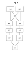
- steps / a1 / and / a2 / can be performed in parallel.
- the branch of steps / b1 / - / c1 / - / d1 / can be performed in parallel with the branch of steps / b2 / - / c2 / - / d2 /.
- the predetermined operating criteria correspond to those previously described with their possible refinements.
- the comparison made in steps / c1 / and / c2 / can take into account, in particular for the static deviation and the dynamic deviation, the movement orders 25,26,27 relating to the motor control of the primary shaft.
Priority Applications (1)
| Application Number | Priority Date | Filing Date | Title |
|---|---|---|---|
| PL12193457T PL2602601T3 (pl) | 2011-12-09 | 2012-11-20 | System monitorowania łańcucha kinematycznego |
Applications Claiming Priority (1)
| Application Number | Priority Date | Filing Date | Title |
|---|---|---|---|
| FR1161427A FR2983957B1 (fr) | 2011-12-09 | 2011-12-09 | Systeme de surveillance de chaine cinematique |
Publications (2)
| Publication Number | Publication Date |
|---|---|
| EP2602601A1 true EP2602601A1 (de) | 2013-06-12 |
| EP2602601B1 EP2602601B1 (de) | 2015-10-21 |
Family
ID=46785455
Family Applications (1)
| Application Number | Title | Priority Date | Filing Date |
|---|---|---|---|
| EP12193457.4A Active EP2602601B1 (de) | 2011-12-09 | 2012-11-20 | Überwachungssystem einer kinematischen Kette |
Country Status (4)
| Country | Link |
|---|---|
| EP (1) | EP2602601B1 (de) |
| ES (1) | ES2557447T3 (de) |
| FR (1) | FR2983957B1 (de) |
| PL (1) | PL2602601T3 (de) |
Citations (3)
| Publication number | Priority date | Publication date | Assignee | Title |
|---|---|---|---|---|
| EP0430297A2 (de) * | 1989-11-30 | 1991-06-05 | Meidensha Kabushiki Kaisha | Verfahren und System zur Prüfung von einer Fahrzeugkraftübertragungseinheit an Motoren und Analyse der Motorausgangscharakteristik über die Übertragungseinheit mittels eines Dynamometers |
| EP1116665A1 (de) * | 2000-01-11 | 2001-07-18 | TOPACK Verpackungstechnik GmbH | Verfahren zur überwachung des verschleisses einer antriebseinrichtung sowie die antriebseinrichtung einer maschine der tabakverarbeitenden industrie |
| US6526816B2 (en) | 2000-12-13 | 2003-03-04 | Eaton Corporation | Transmission gear life monitor system |
-
2011
- 2011-12-09 FR FR1161427A patent/FR2983957B1/fr active Active
-
2012
- 2012-11-20 PL PL12193457T patent/PL2602601T3/pl unknown
- 2012-11-20 EP EP12193457.4A patent/EP2602601B1/de active Active
- 2012-11-20 ES ES12193457.4T patent/ES2557447T3/es active Active
Patent Citations (3)
| Publication number | Priority date | Publication date | Assignee | Title |
|---|---|---|---|---|
| EP0430297A2 (de) * | 1989-11-30 | 1991-06-05 | Meidensha Kabushiki Kaisha | Verfahren und System zur Prüfung von einer Fahrzeugkraftübertragungseinheit an Motoren und Analyse der Motorausgangscharakteristik über die Übertragungseinheit mittels eines Dynamometers |
| EP1116665A1 (de) * | 2000-01-11 | 2001-07-18 | TOPACK Verpackungstechnik GmbH | Verfahren zur überwachung des verschleisses einer antriebseinrichtung sowie die antriebseinrichtung einer maschine der tabakverarbeitenden industrie |
| US6526816B2 (en) | 2000-12-13 | 2003-03-04 | Eaton Corporation | Transmission gear life monitor system |
Also Published As
| Publication number | Publication date |
|---|---|
| ES2557447T3 (es) | 2016-01-26 |
| FR2983957A1 (fr) | 2013-06-14 |
| FR2983957B1 (fr) | 2014-01-24 |
| EP2602601B1 (de) | 2015-10-21 |
| PL2602601T3 (pl) | 2016-04-29 |
Similar Documents
| Publication | Publication Date | Title |
|---|---|---|
| EP2623748B1 (de) | Verfahren und Vorrichtung zur Überprüfung des Zustands eines Turbomotors eines Luftfahrzeugs, das mit mindestens einem Turbomotor ausgestattet ist | |
| EP3712059B1 (de) | Verfahren und vorrichtung zum verschieben des schwerpunktes eines luftfahrzeugs | |
| EP2293429B1 (de) | Gesicherte vorrichtung zur überwachung und steuerung für ein flugzeugsteuerung-stellglied | |
| EP3702269B1 (de) | Haptischer warnmechanismus zur warnung eines piloten eines flugzeugs und flugzeug | |
| EP2551191A1 (de) | Verfahren und Vorrichtung zum Erkennen des Ausfahrens einer Steuerfläche eines Luftfahrzeugs | |
| FR3009540A1 (de) | ||
| FR2713193A1 (fr) | Procédé et dispositif pour détecter un dépassement des charges de dimensionnement d'un aéronef. | |
| FR3012112A1 (fr) | Procede de surveillance de fonctionnement d'un dispositif de pilotage d'aeronef et dispositif de pilotage d'aeronef ainsi surveille | |
| EP2902285B1 (de) | Überwachungsverfahren von mindestens zwei elektromechanischen Bremsstellgliedern | |
| FR3057243A1 (fr) | Organe de commande electrique, aeronef a voilure tournante et procede | |
| FR2986398A1 (fr) | Dispositif de securite pour la commande d'un moteur comprenant une redondance des acquisitions d'une mesure de capteurs | |
| EP2602601B1 (de) | Überwachungssystem einer kinematischen Kette | |
| EP1912103B1 (de) | Verfahren und Vorrichtung zur Überwachung der Servo-Regelung eines Stellglieds | |
| EP2254791B1 (de) | Verfahren und system zur deaktivierung des ausrichtungssystems des vorderen fahrwerks eines flugzeugs | |
| EP2894070A1 (de) | Überwachungsverfahren eines Blockierorgans, und elektromechanisches Stellglied | |
| FR3050309B1 (fr) | Mecanisme d'entrainement d'absorbants de controle de reacteur nucleaire, procede de surveillance et reacteur nucleaire correspondants | |
| FR2975076A1 (fr) | Dispositif de reglage, en particulier dispositif de reglage pour un aeronef | |
| EP2603922B1 (de) | Verfahren und vorrichtung zur steuerung der bewegung eines beweglichen teils eines trennschalters | |
| EP3227981B1 (de) | Verfahren zur detektion des blockieren eines rotors eines ein betätigungsorgan antreibenden motors | |
| EP2762434B1 (de) | System zur Geschwindigkeitssteuerung und -begrenzung für die Bewegungskontrolle eines mobilen Elements | |
| FR3086644A1 (fr) | Procede de detection du blocage d'au moins une girouette d'un aeronef et systeme associe | |
| EP2683579A1 (de) | Verfahren und vorrichtung zur steuerung des elektromotors eines scheibenwischers | |
| FR3130469A1 (fr) | Dispositif de déconnexion d’un générateur entrainé par un rotor, ensemble générateur-moteur associés. | |
| FR2956881A1 (fr) | Systeme de commande-controle de l'angle de calage des pales d'une eolienne | |
| FR2875254A1 (fr) | Procede de controle de fonctionnement d'une porte rapide |
Legal Events
| Date | Code | Title | Description |
|---|---|---|---|
| PUAI | Public reference made under article 153(3) epc to a published international application that has entered the european phase |
Free format text: ORIGINAL CODE: 0009012 |
|
| AK | Designated contracting states |
Kind code of ref document: A1 Designated state(s): AL AT BE BG CH CY CZ DE DK EE ES FI FR GB GR HR HU IE IS IT LI LT LU LV MC MK MT NL NO PL PT RO RS SE SI SK SM TR |
|
| AX | Request for extension of the european patent |
Extension state: BA ME |
|
| 17P | Request for examination filed |
Effective date: 20131212 |
|
| RBV | Designated contracting states (corrected) |
Designated state(s): AL AT BE BG CH CY CZ DE DK EE ES FI FR GB GR HR HU IE IS IT LI LT LU LV MC MK MT NL NO PL PT RO RS SE SI SK SM TR |
|
| GRAP | Despatch of communication of intention to grant a patent |
Free format text: ORIGINAL CODE: EPIDOSNIGR1 |
|
| INTG | Intention to grant announced |
Effective date: 20150508 |
|
| GRAS | Grant fee paid |
Free format text: ORIGINAL CODE: EPIDOSNIGR3 |
|
| GRAA | (expected) grant |
Free format text: ORIGINAL CODE: 0009210 |
|
| AK | Designated contracting states |
Kind code of ref document: B1 Designated state(s): AL AT BE BG CH CY CZ DE DK EE ES FI FR GB GR HR HU IE IS IT LI LT LU LV MC MK MT NL NO PL PT RO RS SE SI SK SM TR |
|
| REG | Reference to a national code |
Ref country code: GB Ref legal event code: FG4D Free format text: NOT ENGLISH |
|
| REG | Reference to a national code |
Ref country code: CH Ref legal event code: EP |
|
| REG | Reference to a national code |
Ref country code: AT Ref legal event code: REF Ref document number: 756897 Country of ref document: AT Kind code of ref document: T Effective date: 20151115 |
|
| REG | Reference to a national code |
Ref country code: IE Ref legal event code: FG4D Free format text: LANGUAGE OF EP DOCUMENT: FRENCH |
|
| REG | Reference to a national code |
Ref country code: DE Ref legal event code: R096 Ref document number: 602012011756 Country of ref document: DE |
|
| REG | Reference to a national code |
Ref country code: FR Ref legal event code: PLFP Year of fee payment: 4 |
|
| REG | Reference to a national code |
Ref country code: RO Ref legal event code: EPE |
|
| REG | Reference to a national code |
Ref country code: ES Ref legal event code: FG2A Ref document number: 2557447 Country of ref document: ES Kind code of ref document: T3 Effective date: 20160126 |
|
| REG | Reference to a national code |
Ref country code: LT Ref legal event code: MG4D |
|
| REG | Reference to a national code |
Ref country code: NL Ref legal event code: FP |
|
| REG | Reference to a national code |
Ref country code: AT Ref legal event code: MK05 Ref document number: 756897 Country of ref document: AT Kind code of ref document: T Effective date: 20151021 |
|
| PG25 | Lapsed in a contracting state [announced via postgrant information from national office to epo] |
Ref country code: HR Free format text: LAPSE BECAUSE OF FAILURE TO SUBMIT A TRANSLATION OF THE DESCRIPTION OR TO PAY THE FEE WITHIN THE PRESCRIBED TIME-LIMIT Effective date: 20151021 Ref country code: NO Free format text: LAPSE BECAUSE OF FAILURE TO SUBMIT A TRANSLATION OF THE DESCRIPTION OR TO PAY THE FEE WITHIN THE PRESCRIBED TIME-LIMIT Effective date: 20160121 Ref country code: IS Free format text: LAPSE BECAUSE OF FAILURE TO SUBMIT A TRANSLATION OF THE DESCRIPTION OR TO PAY THE FEE WITHIN THE PRESCRIBED TIME-LIMIT Effective date: 20160221 Ref country code: LT Free format text: LAPSE BECAUSE OF FAILURE TO SUBMIT A TRANSLATION OF THE DESCRIPTION OR TO PAY THE FEE WITHIN THE PRESCRIBED TIME-LIMIT Effective date: 20151021 |
|
| PG25 | Lapsed in a contracting state [announced via postgrant information from national office to epo] |
Ref country code: RS Free format text: LAPSE BECAUSE OF FAILURE TO SUBMIT A TRANSLATION OF THE DESCRIPTION OR TO PAY THE FEE WITHIN THE PRESCRIBED TIME-LIMIT Effective date: 20151021 Ref country code: LV Free format text: LAPSE BECAUSE OF FAILURE TO SUBMIT A TRANSLATION OF THE DESCRIPTION OR TO PAY THE FEE WITHIN THE PRESCRIBED TIME-LIMIT Effective date: 20151021 Ref country code: PT Free format text: LAPSE BECAUSE OF FAILURE TO SUBMIT A TRANSLATION OF THE DESCRIPTION OR TO PAY THE FEE WITHIN THE PRESCRIBED TIME-LIMIT Effective date: 20160222 Ref country code: SE Free format text: LAPSE BECAUSE OF FAILURE TO SUBMIT A TRANSLATION OF THE DESCRIPTION OR TO PAY THE FEE WITHIN THE PRESCRIBED TIME-LIMIT Effective date: 20151021 Ref country code: AT Free format text: LAPSE BECAUSE OF FAILURE TO SUBMIT A TRANSLATION OF THE DESCRIPTION OR TO PAY THE FEE WITHIN THE PRESCRIBED TIME-LIMIT Effective date: 20151021 Ref country code: GR Free format text: LAPSE BECAUSE OF FAILURE TO SUBMIT A TRANSLATION OF THE DESCRIPTION OR TO PAY THE FEE WITHIN THE PRESCRIBED TIME-LIMIT Effective date: 20160122 |
|
| REG | Reference to a national code |
Ref country code: CH Ref legal event code: PL |
|
| REG | Reference to a national code |
Ref country code: DE Ref legal event code: R097 Ref document number: 602012011756 Country of ref document: DE |
|
| PG25 | Lapsed in a contracting state [announced via postgrant information from national office to epo] |
Ref country code: MC Free format text: LAPSE BECAUSE OF FAILURE TO SUBMIT A TRANSLATION OF THE DESCRIPTION OR TO PAY THE FEE WITHIN THE PRESCRIBED TIME-LIMIT Effective date: 20151021 Ref country code: LI Free format text: LAPSE BECAUSE OF NON-PAYMENT OF DUE FEES Effective date: 20151130 Ref country code: CH Free format text: LAPSE BECAUSE OF NON-PAYMENT OF DUE FEES Effective date: 20151130 |
|
| REG | Reference to a national code |
Ref country code: IE Ref legal event code: MM4A |
|
| PLBE | No opposition filed within time limit |
Free format text: ORIGINAL CODE: 0009261 |
|
| STAA | Information on the status of an ep patent application or granted ep patent |
Free format text: STATUS: NO OPPOSITION FILED WITHIN TIME LIMIT |
|
| PG25 | Lapsed in a contracting state [announced via postgrant information from national office to epo] |
Ref country code: SM Free format text: LAPSE BECAUSE OF FAILURE TO SUBMIT A TRANSLATION OF THE DESCRIPTION OR TO PAY THE FEE WITHIN THE PRESCRIBED TIME-LIMIT Effective date: 20151021 Ref country code: DK Free format text: LAPSE BECAUSE OF FAILURE TO SUBMIT A TRANSLATION OF THE DESCRIPTION OR TO PAY THE FEE WITHIN THE PRESCRIBED TIME-LIMIT Effective date: 20151021 Ref country code: EE Free format text: LAPSE BECAUSE OF FAILURE TO SUBMIT A TRANSLATION OF THE DESCRIPTION OR TO PAY THE FEE WITHIN THE PRESCRIBED TIME-LIMIT Effective date: 20151021 Ref country code: SK Free format text: LAPSE BECAUSE OF FAILURE TO SUBMIT A TRANSLATION OF THE DESCRIPTION OR TO PAY THE FEE WITHIN THE PRESCRIBED TIME-LIMIT Effective date: 20151021 |
|
| 26N | No opposition filed |
Effective date: 20160722 |
|
| PG25 | Lapsed in a contracting state [announced via postgrant information from national office to epo] |
Ref country code: IE Free format text: LAPSE BECAUSE OF NON-PAYMENT OF DUE FEES Effective date: 20151120 |
|
| REG | Reference to a national code |
Ref country code: FR Ref legal event code: PLFP Year of fee payment: 5 |
|
| PG25 | Lapsed in a contracting state [announced via postgrant information from national office to epo] |
Ref country code: SI Free format text: LAPSE BECAUSE OF FAILURE TO SUBMIT A TRANSLATION OF THE DESCRIPTION OR TO PAY THE FEE WITHIN THE PRESCRIBED TIME-LIMIT Effective date: 20151021 |
|
| PG25 | Lapsed in a contracting state [announced via postgrant information from national office to epo] |
Ref country code: HU Free format text: LAPSE BECAUSE OF FAILURE TO SUBMIT A TRANSLATION OF THE DESCRIPTION OR TO PAY THE FEE WITHIN THE PRESCRIBED TIME-LIMIT; INVALID AB INITIO Effective date: 20121120 Ref country code: BG Free format text: LAPSE BECAUSE OF FAILURE TO SUBMIT A TRANSLATION OF THE DESCRIPTION OR TO PAY THE FEE WITHIN THE PRESCRIBED TIME-LIMIT Effective date: 20151021 |
|
| PG25 | Lapsed in a contracting state [announced via postgrant information from national office to epo] |
Ref country code: CY Free format text: LAPSE BECAUSE OF FAILURE TO SUBMIT A TRANSLATION OF THE DESCRIPTION OR TO PAY THE FEE WITHIN THE PRESCRIBED TIME-LIMIT Effective date: 20151021 |
|
| PG25 | Lapsed in a contracting state [announced via postgrant information from national office to epo] |
Ref country code: MT Free format text: LAPSE BECAUSE OF FAILURE TO SUBMIT A TRANSLATION OF THE DESCRIPTION OR TO PAY THE FEE WITHIN THE PRESCRIBED TIME-LIMIT Effective date: 20151021 |
|
| REG | Reference to a national code |
Ref country code: FR Ref legal event code: PLFP Year of fee payment: 6 |
|
| PG25 | Lapsed in a contracting state [announced via postgrant information from national office to epo] |
Ref country code: LU Free format text: LAPSE BECAUSE OF NON-PAYMENT OF DUE FEES Effective date: 20151120 |
|
| PG25 | Lapsed in a contracting state [announced via postgrant information from national office to epo] |
Ref country code: MK Free format text: LAPSE BECAUSE OF FAILURE TO SUBMIT A TRANSLATION OF THE DESCRIPTION OR TO PAY THE FEE WITHIN THE PRESCRIBED TIME-LIMIT Effective date: 20151021 |
|
| PG25 | Lapsed in a contracting state [announced via postgrant information from national office to epo] |
Ref country code: AL Free format text: LAPSE BECAUSE OF FAILURE TO SUBMIT A TRANSLATION OF THE DESCRIPTION OR TO PAY THE FEE WITHIN THE PRESCRIBED TIME-LIMIT Effective date: 20151021 |
|
| PGFP | Annual fee paid to national office [announced via postgrant information from national office to epo] |
Ref country code: PL Payment date: 20221018 Year of fee payment: 11 Ref country code: BE Payment date: 20221125 Year of fee payment: 11 |
|
| PGFP | Annual fee paid to national office [announced via postgrant information from national office to epo] |
Ref country code: NL Payment date: 20231023 Year of fee payment: 12 |
|
| PGFP | Annual fee paid to national office [announced via postgrant information from national office to epo] |
Ref country code: GB Payment date: 20231120 Year of fee payment: 12 |
|
| PGFP | Annual fee paid to national office [announced via postgrant information from national office to epo] |
Ref country code: ES Payment date: 20231218 Year of fee payment: 12 |
|
| PGFP | Annual fee paid to national office [announced via postgrant information from national office to epo] |
Ref country code: TR Payment date: 20231108 Year of fee payment: 12 Ref country code: RO Payment date: 20231101 Year of fee payment: 12 Ref country code: IT Payment date: 20231109 Year of fee payment: 12 Ref country code: FR Payment date: 20231023 Year of fee payment: 12 Ref country code: FI Payment date: 20231020 Year of fee payment: 12 Ref country code: DE Payment date: 20231107 Year of fee payment: 12 Ref country code: CZ Payment date: 20231020 Year of fee payment: 12 |
|
| PGFP | Annual fee paid to national office [announced via postgrant information from national office to epo] |
Ref country code: PL Payment date: 20231030 Year of fee payment: 12 Ref country code: BE Payment date: 20231113 Year of fee payment: 12 |