US4479558A - Drilling sub - Google Patents
Drilling sub Download PDFInfo
- Publication number
- US4479558A US4479558A US06/290,296 US29029681A US4479558A US 4479558 A US4479558 A US 4479558A US 29029681 A US29029681 A US 29029681A US 4479558 A US4479558 A US 4479558A
- Authority
- US
- United States
- Prior art keywords
- transverse
- nozzle
- housing
- passageway
- transverse opening
- Prior art date
- Legal status (The legal status is an assumption and is not a legal conclusion. Google has not performed a legal analysis and makes no representation as to the accuracy of the status listed.)
- Expired - Fee Related
Links
- 238000005553 drilling Methods 0.000 title claims abstract description 49
- 239000012530 fluid Substances 0.000 claims abstract description 24
- 238000007789 sealing Methods 0.000 claims description 4
- 238000010276 construction Methods 0.000 abstract description 6
- 230000015572 biosynthetic process Effects 0.000 description 5
- 238000005520 cutting process Methods 0.000 description 4
- 230000003628 erosive effect Effects 0.000 description 2
- 230000007423 decrease Effects 0.000 description 1
- 230000001788 irregular Effects 0.000 description 1
- 239000003129 oil well Substances 0.000 description 1
- 230000035515 penetration Effects 0.000 description 1
Images
Classifications
-
- E—FIXED CONSTRUCTIONS
- E21—EARTH DRILLING; MINING
- E21B—EARTH DRILLING, e.g. DEEP DRILLING; OBTAINING OIL, GAS, WATER, SOLUBLE OR MELTABLE MATERIALS OR A SLURRY OF MINERALS FROM WELLS
- E21B41/00—Equipment or details not covered by groups E21B15/00 - E21B40/00
- E21B41/0078—Nozzles used in boreholes
-
- E—FIXED CONSTRUCTIONS
- E21—EARTH DRILLING; MINING
- E21B—EARTH DRILLING, e.g. DEEP DRILLING; OBTAINING OIL, GAS, WATER, SOLUBLE OR MELTABLE MATERIALS OR A SLURRY OF MINERALS FROM WELLS
- E21B21/00—Methods or apparatus for flushing boreholes, e.g. by use of exhaust air from motor
- E21B21/12—Methods or apparatus for flushing boreholes, e.g. by use of exhaust air from motor using drilling pipes with plural fluid passages, e.g. closed circulation systems
Definitions
- This invention relates generally to apparatus for drilling oil wells, and more particularly to an improved drilling sub of the type constructed to be used in connection with a drill bit for creating a vortex in a borehole adjacent the drill bit.
- the present invention is an improved version of the structure disclosed in U.S. patent application Ser. No. 169,676 of Hayatdavoudi et al., filed July 17, 1980 for DOWNHOLE VORTEX GENERATOR and assigned to the assignee of the present invention.
- the structure disclosed in the Hayatdavoudi et al. application includes a drilling sub having a cylindrical housing with an upper end adapted to be connected to a drill string and a lower end adapted to be connected to a drill bit.
- An open cavity is disposed in the outer cylindrical surface of the housing.
- a longitudinal passageway is disposed through the housing.
- a transverse passageway means is disposed in the housing with a first end communicated with the longitudinal passageway and a second end communicated with the open cavity, for taking a portion of drilling fluid from the longitudinal passageway and for ejecting said portion of drilling fluid from the second end of the transverse passageway means with a non-radial velocity component in a plane normal to a longitudinal axis of the housing.
- the present invention provides an improved drilling apparatus having a much simplified construction and arrangement of the transverse passageway means including a transverse opening and a nozzle disposed in the transverse opening.
- the transverse passageway means has a first end substantially tangentially intersecting the longitudinal passageway and has a second end communicated with the open cavity.
- the transverse opening is a straight cylindrical transverse opening having a first end thereof substantially tangentially intersecting the longitudinal passageway.
- the nozzle is preferably a shrouded drill bit-type nozzle having a linear portion of the transverse passageway disposed therethrough.
- FIG. 1 is a schematic elevation view of a rotary drill string with a drilling sub and rotary drill bit attached thereto in place within a well borehole.
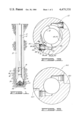
- FIG. 2 is an elevation section view of the improved drilling sub of the present invention.
- FIG. 3 is an irregular sectional view taken along line 3--3 of FIG. 2. It is noted that FIG. 3 is not a true section along line 3--3, but rather it is a horizontal section through the enlarged part of the longitudinal passageway, with a section through the transverse passageway projected thereon.
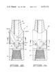
- FIG. 4 is an elevation section view of an alternative embodiment of thedrilling sub of the present invention.
- FIG. 5 is a sectional view taken along line 5--5 of FIG. 4, in a manner similar to FIG. 3.
- a drill string 10 is shown in place within a well borehole 12.
- the drill string 10 is comprised of a plurality of pipe segments and other apparatus threadedly connected together and rotated by a rotary drilling rig located at the ground surface.
- the drilling sub 14 of the present invention Connected to the lower end of the drill string 10 is the drilling sub 14 of the present invention, to the lower end of which is connected a rotary drill bit 16.
- the drilling sub 14 itself may be considered to be a part of the drill string 10.
- the cutting edge of the drill bit 16 is shown in contact with a face 18 of an underground formation 20 into which the drill bit 16 drills as the drill string 10 is rotated.
- annulus 22 Defined between the drill string 10 and the borehole 12 is an annulus 22.
- drilling mud is pumped down an internal bore of the drill string 10 and flows out jet openings 24 between the cones 26 of the drill bit 16 so as to flush away cuttings and other debris from the teeth of the cones and from the interface between the drill bit 16 and the face 18 of the formation. This drilling fluid then flows back upward through the annulus 22 to carry the cuttings away from the drill bit 16.
- FIG. 2 a sectional elevation view of the drilling sub 14 is thereshown.
- the drilling sub 14 includes a cylindrical housing 28 having a threaded upper pin end 30 adapted to be connected to drill string 10 and having an internally threaded tapered lower box end 32 adapted to be connected to drill bit 16.
- Housing 28 includes an outer cylindrical surface 34 within which are disposed first and second open cavities 36 and 38.
- First open cavity 36 is defined by an arcuate surface 40 and a flat surface 42.
- Second open cavity 38 is defined by an arcuate surface 44 and a flat surface 46.
- a longitudinal passageway 48 is disposed through housing 28 and includes an enlarged inner diameter cylindrical surface 50.
- An inner diameter of the enlarged inner diameter cylindrical surface 50 is greater than an inner diameter of an upper portion 52 of internally threaded tapered box end 32 of housing 28.
- First and second straight cylindrical transverse openings 54 and 56 are disposed in housing 28 for communicating longitudinal passageway 48 with first and second open cavities 36 and 38, respectively. Openings 54 and 56 are preferably oriented at an angle 57 in the range of about 30° to 60°.
- the transverse openings 54 and 56 have first and second nozzles 58 and 60, respectively, received therein.
- Transverse opening 54 has a first end 62 substantially tangentially intersecting enlarged portion 50 of longitudinal passageway 48 and has a second end 64 communicated with flat surface 42 of open cavity 36.
- First straight cylindrical transverse opening 54 includes a bore 66 and a counterbore 68. Bore 66 and counterbore 68 are connected by a shoulder 70.
- annular locking groove 72 Disposed in counterbore 68 are an annular locking groove 72 and an annular sealing groove 74.
- Nozzle 58 has an inlet 76 and a restricted outlet 78.
- An inner diameter of the restricted outlet 78 is smaller than an inner diameter of the inlet 70.
- Inlet 76 and outlet 78 are connected by a linear nozzle passage 80.
- the nozzle passage 80 is said to be "linear” because a central axis of inlet 76 is coincident with a central axis of outlet 78.
- the linear nozzle passage 80 and the portion of transverse opening 54 located between inlet 76 of nozzle 58 and the longitudinal passageway 48 of housing 28 comprise a transverse passageway means 82.
- the transverse passageway means 82 may be described as being disposed in the housing 28 and having a first end, i.e., first end 62 of transverse opening 54, substantially tangentially intersecting the enlarged portion 50 of longitudinal passageway 48 for taking a portion of drilling fluid from the longitudinal passageway 48 and having a second end, i.e., the restricted outlet 78 of nozzle 58, communicated with the open cavity 36 for ejecting the portion of drilling fluid taken from the longitudinal passageway 48 from the second end 78 of the transverse passageway means with a non-radial velocity component in a plane normal to a longitudinal axis of the housing 28.
- the longitudinal axis of the housing 28 is a central axis of the longitudinal passageway 48.
- a longitudinal axis 83 of the straight cylindrical transverse opening 54 tangentially intersects an enlarged inner cylindrical surface 50 of longitudinal passageway 48.
- the structural relationship defined by the term "substantially tangential" does not, however, necessarily require that a central axis of the transverse opening be exactly tangential to an inner cylindrical surface of the longitudinal passageway 48, but rather only requires that the central axis of the transverse opening be horizontally offset from the longitudinal axis of the longitudinal passageway 48 by a substantial portion of the magnitude of a radius of the inner cylindrical surface 50 of the longitudinal passageway 48 so that the drilling fluid exiting the restricted outlet 78 will have a substantial component of its velocity oriented tangential to the annulus 22.
- the non-radial velocity component of the portion of drilling fluid injected into the annulus 22 is in the clockwise direction about the longitudinal axis of the housing 28 when viewed from above.
- the transverse passageways be oriented as shown so as to provide this clockwise motion of the drilling fluid ejected into the annulus 22 in order to prevent the imposition of any forces upon the drill string 10 which might tend to unthread the components of the drill string 10
- the drilling sub 14 may be constructed with a transverse passageway means oriented 180° from that shown so as to provide a counterclockwise motion of drilling fluid within the annulus 22 as viewed from above.
- the nozzle 58 is held in place within counterbore 68 of first straight cylindrical transverse opening 54 by a resilient locking ring means 84.
- a portion 86 of nozzle 58 extending outward beyond locking ring 84 is defined as a shroud means 86 for covering an outer side of the locking ring means 84 to protect the locking ring means 84 from erosion. This erosion is believed to be caused by a relatively small but strong vortex flow immediately adjacent the outlets of the nozzles.
- the shroud 86 shields locking ring means 84 from this vortex flow.
- a resilient O-ring seal 88 is disposed in sealing groove 74 for sealing between the nozzle 58 and the counterbore 68 of transverse opening 54.
- a flat outer end surface 90 of shroud 86 is substantially flush with flat surface 42 of open cavity 36.
- nozzle 58 abuts or is only very slightly displaced from shoulder 70.
- the construction of the nozzle 58 is such that the clearances between lock ring 84 and groove 72 allow the inner end of nozzle 58 to engage shoulder 70 if the pressure exterior of the housing 28 is greater than that in passageway 48, thereby preventing excess loading on the lock ring 84.
- the open cavity 36 and the nozzle outlet 78 are so arranged and constructed that the portion of drilling fluid taken from the longitudinal passageway 48 is ejected from the restricted outlet 78 of the nozzle 58 directly through the open cavity 36 into the annulus 22 surrounding the cylindrical housing 28 without any substantial impingement upon any structure connected to the housing 28.
- FIGS. 4 and 5 an alternative embodiment of the present invention is thereshown, with like structural elements carrying the same numbers as the corresponding structure of FIGS. 2 and 3.
- the enlarged diameter portion 50A of longitudinal passageway 48A is not greater than the inner diameter of the upper portion 52 of threaded box 32.
- This construction is generally used for drilling subs of smaller sizes, e.g., 6" O.D. and smaller.
- cavities 36A and 38A have a somewhat different configuration than cavities 36 and 38.
- the drilling sub 14 of the present invention is utilized and functions in the following manner.
- the drill string 10 is rotated at its upper end thus rotating the drill bit 16 and boring the wellbore 12 into the formation 20.
- Drilling fluid such as drilling mud
- This downward flowing stream of drilling mud is divided at a junction between the transverse opening 54 and the longitudinal passageway 48 at a first elevation 92 (see FIG. 1) above the drill bit 16 into a first stream and a second stream.
- the second stream of drilling mud is directed downward through the lower portion of longitudinal passageway 48 to the drill bit 16 then out the jet orifices 26 of the drill bit 16 and upward through the annulus 22 between the drill string 10 and the borehole 12.
- the first stream of drilling fluid is directed through the transverse passageway means 82 into the annulus 22 at a second elevation 94 above the drill bit 16 with a velocity component tangential to the annulus 22.
- This tangential velocity component of the first stream of drilling fluid imparts a clockwise swirling motion as viewed from above about the drill string 10 to the upward flowing second stream of drilling fluid in the annulus 22.
- the first stream of drilling fluid exiting the restricted outlet 78 of transverse passageway means 82 also has an upward velocity component such that an upwardly swirling motion is imparted to the fluid in annulus 22.
- a sufficient swirling motion is imparted to the drilling mud in annulus 22 abo ut the drill string 10 to create a vortex in the upward flowing drilling fluid, which vortex extends downward to the drill bit 16 and the face 18 of the formation against which the drill bit 16 is cutting.
- This vortex decreases a fluid pressure in the borehole at the face 18 between the drill bit 16 and underground formation 20 to thereby increase a penetration rate of the drill bit as compared to rates achievable in the absence of the swirling motion of the drilling fluid.
Abstract
An improved construction is provided for a transverse passageway and a nozzle of a drilling sub of the type used to eject drilling fluid from the transverse passageway to create a vortex in an annulus surrounding the drilling sub.
Description
1. Field of the Invention
This invention relates generally to apparatus for drilling oil wells, and more particularly to an improved drilling sub of the type constructed to be used in connection with a drill bit for creating a vortex in a borehole adjacent the drill bit.
2. Description of the Prior Art
The present invention is an improved version of the structure disclosed in U.S. patent application Ser. No. 169,676 of Hayatdavoudi et al., filed July 17, 1980 for DOWNHOLE VORTEX GENERATOR and assigned to the assignee of the present invention.
The structure disclosed in the Hayatdavoudi et al. application includes a drilling sub having a cylindrical housing with an upper end adapted to be connected to a drill string and a lower end adapted to be connected to a drill bit. An open cavity is disposed in the outer cylindrical surface of the housing. A longitudinal passageway is disposed through the housing. A transverse passageway means is disposed in the housing with a first end communicated with the longitudinal passageway and a second end communicated with the open cavity, for taking a portion of drilling fluid from the longitudinal passageway and for ejecting said portion of drilling fluid from the second end of the transverse passageway means with a non-radial velocity component in a plane normal to a longitudinal axis of the housing.
One difficulty encountered with the apparatus of the Hayatdavoudi et al. application is the complexity of construction of the transverse passageway means.
The present invention provides an improved drilling apparatus having a much simplified construction and arrangement of the transverse passageway means including a transverse opening and a nozzle disposed in the transverse opening. The transverse passageway means has a first end substantially tangentially intersecting the longitudinal passageway and has a second end communicated with the open cavity. The transverse opening is a straight cylindrical transverse opening having a first end thereof substantially tangentially intersecting the longitudinal passageway. The nozzle is preferably a shrouded drill bit-type nozzle having a linear portion of the transverse passageway disposed therethrough.
Numerous objects, features and advantages of the present invention will be readily apparent to those skilled in the art upon a reading of the following disclosure when taken in conjunction with the accompanying drawings.
FIG. 1 is a schematic elevation view of a rotary drill string with a drilling sub and rotary drill bit attached thereto in place within a well borehole.
FIG. 2 is an elevation section view of the improved drilling sub of the present invention.
FIG. 3 is an irregular sectional view taken along line 3--3 of FIG. 2. It is noted that FIG. 3 is not a true section along line 3--3, but rather it is a horizontal section through the enlarged part of the longitudinal passageway, with a section through the transverse passageway projected thereon.
FIG. 4 is an elevation section view of an alternative embodiment of thedrilling sub of the present invention.
FIG. 5 is a sectional view taken along line 5--5 of FIG. 4, in a manner similar to FIG. 3.
Referring now to the drawings, and particularly to FIG. 1, a drill string 10 is shown in place within a well borehole 12.
Those skilled in the art will understand that the drill string 10 is comprised of a plurality of pipe segments and other apparatus threadedly connected together and rotated by a rotary drilling rig located at the ground surface.
Connected to the lower end of the drill string 10 is the drilling sub 14 of the present invention, to the lower end of which is connected a rotary drill bit 16. The drilling sub 14 itself may be considered to be a part of the drill string 10. The cutting edge of the drill bit 16 is shown in contact with a face 18 of an underground formation 20 into which the drill bit 16 drills as the drill string 10 is rotated.
Defined between the drill string 10 and the borehole 12 is an annulus 22.
During typical drilling operations without the drilling sub 14 of the present invention, drilling mud is pumped down an internal bore of the drill string 10 and flows out jet openings 24 between the cones 26 of the drill bit 16 so as to flush away cuttings and other debris from the teeth of the cones and from the interface between the drill bit 16 and the face 18 of the formation. This drilling fluid then flows back upward through the annulus 22 to carry the cuttings away from the drill bit 16.
Referring now to FIG. 2, a sectional elevation view of the drilling sub 14 is thereshown.
The drilling sub 14 includes a cylindrical housing 28 having a threaded upper pin end 30 adapted to be connected to drill string 10 and having an internally threaded tapered lower box end 32 adapted to be connected to drill bit 16.
Housing 28 includes an outer cylindrical surface 34 within which are disposed first and second open cavities 36 and 38. First open cavity 36 is defined by an arcuate surface 40 and a flat surface 42. Second open cavity 38 is defined by an arcuate surface 44 and a flat surface 46.
A longitudinal passageway 48 is disposed through housing 28 and includes an enlarged inner diameter cylindrical surface 50.
An inner diameter of the enlarged inner diameter cylindrical surface 50 is greater than an inner diameter of an upper portion 52 of internally threaded tapered box end 32 of housing 28.
First and second straight cylindrical transverse openings 54 and 56 are disposed in housing 28 for communicating longitudinal passageway 48 with first and second open cavities 36 and 38, respectively. Openings 54 and 56 are preferably oriented at an angle 57 in the range of about 30° to 60°.
As shown in FIG. 3, the transverse openings 54 and 56 have first and second nozzles 58 and 60, respectively, received therein.
Transverse opening 54 has a first end 62 substantially tangentially intersecting enlarged portion 50 of longitudinal passageway 48 and has a second end 64 communicated with flat surface 42 of open cavity 36.
First straight cylindrical transverse opening 54 includes a bore 66 and a counterbore 68. Bore 66 and counterbore 68 are connected by a shoulder 70.
Disposed in counterbore 68 are an annular locking groove 72 and an annular sealing groove 74.
Nozzle 58 has an inlet 76 and a restricted outlet 78. An inner diameter of the restricted outlet 78 is smaller than an inner diameter of the inlet 70. Inlet 76 and outlet 78 are connected by a linear nozzle passage 80. The nozzle passage 80 is said to be "linear" because a central axis of inlet 76 is coincident with a central axis of outlet 78.
The linear nozzle passage 80 and the portion of transverse opening 54 located between inlet 76 of nozzle 58 and the longitudinal passageway 48 of housing 28 comprise a transverse passageway means 82. The transverse passageway means 82 may be described as being disposed in the housing 28 and having a first end, i.e., first end 62 of transverse opening 54, substantially tangentially intersecting the enlarged portion 50 of longitudinal passageway 48 for taking a portion of drilling fluid from the longitudinal passageway 48 and having a second end, i.e., the restricted outlet 78 of nozzle 58, communicated with the open cavity 36 for ejecting the portion of drilling fluid taken from the longitudinal passageway 48 from the second end 78 of the transverse passageway means with a non-radial velocity component in a plane normal to a longitudinal axis of the housing 28. The longitudinal axis of the housing 28 is a central axis of the longitudinal passageway 48.
In the embodiment of FIG. 3, a longitudinal axis 83 of the straight cylindrical transverse opening 54 tangentially intersects an enlarged inner cylindrical surface 50 of longitudinal passageway 48. The structural relationship defined by the term "substantially tangential" does not, however, necessarily require that a central axis of the transverse opening be exactly tangential to an inner cylindrical surface of the longitudinal passageway 48, but rather only requires that the central axis of the transverse opening be horizontally offset from the longitudinal axis of the longitudinal passageway 48 by a substantial portion of the magnitude of a radius of the inner cylindrical surface 50 of the longitudinal passageway 48 so that the drilling fluid exiting the restricted outlet 78 will have a substantial component of its velocity oriented tangential to the annulus 22.
The non-radial velocity component of the portion of drilling fluid injected into the annulus 22 is in the clockwise direction about the longitudinal axis of the housing 28 when viewed from above. Although it is preferred that the transverse passageways be oriented as shown so as to provide this clockwise motion of the drilling fluid ejected into the annulus 22 in order to prevent the imposition of any forces upon the drill string 10 which might tend to unthread the components of the drill string 10, the drilling sub 14 may be constructed with a transverse passageway means oriented 180° from that shown so as to provide a counterclockwise motion of drilling fluid within the annulus 22 as viewed from above.
The nozzle 58 is held in place within counterbore 68 of first straight cylindrical transverse opening 54 by a resilient locking ring means 84. A portion 86 of nozzle 58 extending outward beyond locking ring 84 is defined as a shroud means 86 for covering an outer side of the locking ring means 84 to protect the locking ring means 84 from erosion. This erosion is believed to be caused by a relatively small but strong vortex flow immediately adjacent the outlets of the nozzles. The shroud 86 shields locking ring means 84 from this vortex flow.
A resilient O-ring seal 88 is disposed in sealing groove 74 for sealing between the nozzle 58 and the counterbore 68 of transverse opening 54.
A flat outer end surface 90 of shroud 86 is substantially flush with flat surface 42 of open cavity 36.
The inner end of nozzle 58 abuts or is only very slightly displaced from shoulder 70. The construction of the nozzle 58 is such that the clearances between lock ring 84 and groove 72 allow the inner end of nozzle 58 to engage shoulder 70 if the pressure exterior of the housing 28 is greater than that in passageway 48, thereby preventing excess loading on the lock ring 84.
The open cavity 36 and the nozzle outlet 78 are so arranged and constructed that the portion of drilling fluid taken from the longitudinal passageway 48 is ejected from the restricted outlet 78 of the nozzle 58 directly through the open cavity 36 into the annulus 22 surrounding the cylindrical housing 28 without any substantial impingement upon any structure connected to the housing 28.
Referring now to FIGS. 4 and 5, an alternative embodiment of the present invention is thereshown, with like structural elements carrying the same numbers as the corresponding structure of FIGS. 2 and 3.
In the drilling sub 14A of FIGS. 4 and 5, the enlarged diameter portion 50A of longitudinal passageway 48A, is not greater than the inner diameter of the upper portion 52 of threaded box 32. This construction is generally used for drilling subs of smaller sizes, e.g., 6" O.D. and smaller.
Also, the open cavities 36A and 38A have a somewhat different configuration than cavities 36 and 38.
The drilling sub 14 of the present invention is utilized and functions in the following manner. The drill string 10 is rotated at its upper end thus rotating the drill bit 16 and boring the wellbore 12 into the formation 20. Drilling fluid, such as drilling mud, is directed down an internal bore of the drill string 10. This downward flowing stream of drilling mud is divided at a junction between the transverse opening 54 and the longitudinal passageway 48 at a first elevation 92 (see FIG. 1) above the drill bit 16 into a first stream and a second stream. The second stream of drilling mud is directed downward through the lower portion of longitudinal passageway 48 to the drill bit 16 then out the jet orifices 26 of the drill bit 16 and upward through the annulus 22 between the drill string 10 and the borehole 12.
The first stream of drilling fluid is directed through the transverse passageway means 82 into the annulus 22 at a second elevation 94 above the drill bit 16 with a velocity component tangential to the annulus 22. This tangential velocity component of the first stream of drilling fluid imparts a clockwise swirling motion as viewed from above about the drill string 10 to the upward flowing second stream of drilling fluid in the annulus 22.
The first stream of drilling fluid exiting the restricted outlet 78 of transverse passageway means 82 also has an upward velocity component such that an upwardly swirling motion is imparted to the fluid in annulus 22.
A sufficient swirling motion is imparted to the drilling mud in annulus 22 abo ut the drill string 10 to create a vortex in the upward flowing drilling fluid, which vortex extends downward to the drill bit 16 and the face 18 of the formation against which the drill bit 16 is cutting. This vortex decreases a fluid pressure in the borehole at the face 18 between the drill bit 16 and underground formation 20 to thereby increase a penetration rate of the drill bit as compared to rates achievable in the absence of the swirling motion of the drilling fluid.
Thus it is seen that the apparatus of the present invention readily achieves the ends and advantages mentioned as well as those inherent therein. While certain preferred embodiments of the invention have been illustrated for the purposes of the present disclosure, numerous changes in the arrangement and construction of parts may be made by those skilled in the art, which changes are embodied within the scope and spirit of the present invention as defined by the appended claims.
Claims (12)
1. A drilling apparatus, comprising:
a cylindrical housing having an upper end adapted to be connected to a drill string and a lower end adapted to be connected to a drill bit;
an open cavity disposed in an outer cylindrical surface of said housing;
a longitudinal passageway disposed through said housing;
a transverse passageway means, disposed in said housing and having a first end substantially tangentially intersecting said longitudinal passageway for taking a portion of drilling fluid from said longitudinal passageway, and having a second end communicated with said open cavity for ejecting said portion of drilling fluid from said second end of said transverse passageway means with a non-radial velocity component in a plane normal to a longitudingal axis of said housing;
wherein said housing has a straight cylindrical transverse opening disposed therein with a first end of said transverse opening substantially tangentially intersecting said longitudinal passageway and with a second end of said transverse opening communicated with said open cavity, and wherein a longitudinal axis of said straight cylindrical transverse opening tangentially intersects and inner cylindrical surface of said longitudinal passageway; and
wherein said drilling apparatus further includes a nozzle disposed in said transverse opening, said nozzle having an inlet and a restricted outlet and having at least a portion of said transverse passageway means disposed therethrough connecting said inlet and restricted outlet, an inner diameter of said restricted outlet being smaller than an inner diameter of said inlet.
2. The apparatus of claim 1, wherein:
said first end of said transverse passageway means is defined by said first end of said straight cylindrical transverse opening.
3. The apparatus of claim 1, further comprising:
a locking groove disposed in said transverse opening; and
a resilient locking ring means received in said locking groove for holding said nozzle in said transverse opening.
4. The apparatus of claim 3, wherein:
said nozzle includes a shroud means for covering said locking ring means.
5. The apparatus of claim 4, wherein:
said open cavity is partially defined by a flat surface intersecting said second end of said transverse opening; and
a flat outer end surface of said shroud means is substantially flush with said flat surface of said open cavity.
6. The apparatus of claim 1, further comprising:
annular resilient seal means between said nozzle and said transverse opening.
7. The apparatus of claim 6, wherein:
said seal means includes an elastomeric O-ring received in an annular sealing groove disposed in said transverse opening.
8. The apparatus of claim 1, wherein:
said open cavity and said nozzle outlet are so arranged and constructed that said portion of drilling fluid is ejected from said restricted outlet of said nozzle directly through said open cavity into an annulus surrounding said cylindrical housing without any substantial impingement upon any structure connected to said housing.
9. The apparatus of claim 1, wherein:
said portion of said transverse passageway means disposed through said nozzle is a linear portion such that a central axis of said inlet of said nozzle is coincident with said cnetral axis of said second end of said transverse passageway means, said second end of said transverse passageway means being said restricted outlet of said nozzle.
10. The apparatus of claim 1, wherein:
said inner cylindrical surface of said longitudinal passageway is further characterized as being an enlarged inner diameter portion of said longitudinal passageway.
11. The apparatus of claim 10, wherein:
said lower end of said cylindrical housing includes an internally threaded tapered box; and
said enlarged diameter inner cylindrical surface of said longitudinal passageway has an inner diameter greater than an inner diameter of an upper end of said tapered box.
12. The apparatus of claim 1, wherein:
said non-radial velocity component of said portion of drilling fluid ejected from said second end of said transverse passageway means is in a clockwise direction about said longitudinal axis of said housing when viewed from above.
Priority Applications (2)
| Application Number | Priority Date | Filing Date | Title |
|---|---|---|---|
| US06/290,296 US4479558A (en) | 1981-08-05 | 1981-08-05 | Drilling sub |
| CA000398229A CA1166627A (en) | 1981-08-05 | 1982-03-12 | Drilling sub |
Applications Claiming Priority (1)
| Application Number | Priority Date | Filing Date | Title |
|---|---|---|---|
| US06/290,296 US4479558A (en) | 1981-08-05 | 1981-08-05 | Drilling sub |
Publications (1)
| Publication Number | Publication Date |
|---|---|
| US4479558A true US4479558A (en) | 1984-10-30 |
Family
ID=23115360
Family Applications (1)
| Application Number | Title | Priority Date | Filing Date |
|---|---|---|---|
| US06/290,296 Expired - Fee Related US4479558A (en) | 1981-08-05 | 1981-08-05 | Drilling sub |
Country Status (2)
| Country | Link |
|---|---|
| US (1) | US4479558A (en) |
| CA (1) | CA1166627A (en) |
Cited By (14)
| Publication number | Priority date | Publication date | Assignee | Title |
|---|---|---|---|---|
| GB2162881A (en) * | 1984-08-08 | 1986-02-12 | Total Petroles | A drill pipe joint |
| EP0257944A2 (en) * | 1986-08-21 | 1988-03-02 | Smith International (North Sea) Limited | Milling tool |
| US5029657A (en) * | 1989-11-14 | 1991-07-09 | Arthur Mahar | Rock drill bit |
| GB2287051A (en) * | 1994-02-28 | 1995-09-06 | Smith International | Flow control sub for hydraulic expanding downhole tools |
| EP0754836A1 (en) * | 1995-07-19 | 1997-01-22 | Halliburton Company | Method and apparatus for removing gelled drilling fluid and filter cake from the side of a well bore |
| US20050045382A1 (en) * | 1999-02-25 | 2005-03-03 | Weatherford/Lamb, Inc. | Apparatus and method to reduce fluid pressure in a wellbore |
| US6968911B2 (en) | 1999-02-25 | 2005-11-29 | Weatherford/Lamb, Inc. | Apparatus and methods for drilling |
| US20060005999A1 (en) * | 2003-06-26 | 2006-01-12 | Butler Bryan V | Methods and apparatus for drilling with a multiphase pump |
| US20060283636A1 (en) * | 2005-06-21 | 2006-12-21 | Reagan Loren P | Fluid driven drilling motor and system |
| WO2007108692A1 (en) * | 2006-03-21 | 2007-09-27 | Seashore Technology As | Washing tool and method for cleaning wells and onshore/offshore boring equipment |
| US20090279966A1 (en) * | 2008-05-12 | 2009-11-12 | Baker Hughes Incorporated | Reverse flow mill |
| US20100101867A1 (en) * | 2008-10-27 | 2010-04-29 | Olivier Sindt | Self-stabilized and anti-whirl drill bits and bottom-hole assemblies and systems for using the same |
| WO2017220098A1 (en) | 2016-06-22 | 2017-12-28 | Advancetech Aps | Downhole tool with directional nozzle and a drill string thereof |
| US10087686B2 (en) * | 2015-06-04 | 2018-10-02 | Sandvik Intellectual Property Ab | Shank adaptor with strengthened flushing hole |
Citations (31)
| Publication number | Priority date | Publication date | Assignee | Title |
|---|---|---|---|---|
| US890978A (en) * | 1907-04-13 | 1908-06-16 | Martin Hardsocg | Pneumatic drill. |
| US2286258A (en) * | 1940-03-27 | 1942-06-16 | Bubenic Louis | Sanitary tail tie |
| US2340738A (en) * | 1941-05-01 | 1944-02-01 | Smith Corp A O | Turbine driven well drilling unit |
| US2365941A (en) * | 1942-08-31 | 1944-12-26 | Shell Dev | Oil well drill bit |
| US2485098A (en) * | 1948-04-23 | 1949-10-18 | Johnson Ture | Structure drill |
| US2545195A (en) * | 1946-08-24 | 1951-03-13 | Shell Dev | Diamond bit |
| US2626780A (en) * | 1951-06-06 | 1953-01-27 | Standard Oil Dev Co | Double-acting drill bit |
| US2634101A (en) * | 1949-07-08 | 1953-04-07 | Sloan Pearl | Apparatus for accelerating the removal of cuttings from the bottom of wells |
| US2643094A (en) * | 1949-12-05 | 1953-06-23 | Reed Roller Bit Co | Drilling method and apparatus |
| US2710741A (en) * | 1950-07-28 | 1955-06-14 | Sr Jesse E Hall | Apparatus for drilling or hole testing |
| US2738167A (en) * | 1953-04-06 | 1956-03-13 | Jr Edward B Williams | Combined reamer and core bit |
| US2765146A (en) * | 1952-02-09 | 1956-10-02 | Jr Edward B Williams | Jetting device for rotary drilling apparatus |
| US2776115A (en) * | 1953-10-29 | 1957-01-01 | Jr Edward B Williams | Drill bit |
| US2805045A (en) * | 1953-06-08 | 1957-09-03 | Globe Oil Tools Co | Well drilling bit |
| US2861780A (en) * | 1956-06-20 | 1958-11-25 | Jimmy L Butler | Means for cooling the cutters of drill bits |
| US2946565A (en) * | 1953-06-16 | 1960-07-26 | Jersey Prod Res Co | Combination drilling and testing process |
| US3111179A (en) * | 1960-07-26 | 1963-11-19 | A And B Metal Mfg Company Inc | Jet nozzle |
| US3144087A (en) * | 1961-01-05 | 1964-08-11 | Edward B Williams Iii | Drill bit with tangential jet |
| US3198256A (en) * | 1961-10-09 | 1965-08-03 | Bowen Tools Inc | Jet junk basket |
| US3215215A (en) * | 1962-08-27 | 1965-11-02 | Exxon Production Research Co | Diamond bit |
| US3455402A (en) * | 1967-03-13 | 1969-07-15 | Inst Francais Du Petrole | Drilling device |
| US3908771A (en) * | 1974-03-01 | 1975-09-30 | Wylie P Garrett | Drill collar incorporating device for jetting drilling fluid transversely into bore hole |
| US3923109A (en) * | 1975-02-24 | 1975-12-02 | Jr Edward B Williams | Drill tool |
| US3958651A (en) * | 1975-07-31 | 1976-05-25 | Dresser Industries, Inc. | Vacuum, vacuum-pressure, or pressure circulation bit having jet-assisted vacuum |
| US4022285A (en) * | 1976-03-11 | 1977-05-10 | Frank Donald D | Drill bit with suction and method of dry drilling with liquid column |
| US4083417A (en) * | 1976-11-12 | 1978-04-11 | Arnold James F | Jetting apparatus |
| US4126194A (en) * | 1977-07-11 | 1978-11-21 | Smith International, Inc. | Rock bit with extended pickup tube |
| US4222447A (en) * | 1977-11-21 | 1980-09-16 | Institut Francais Du Petrole | Drill bit with suction jets |
| US4223747A (en) * | 1977-10-27 | 1980-09-23 | Compagnie Francaise Des Petroles | Drilling using reverse circulation |
| US4239087A (en) * | 1977-01-28 | 1980-12-16 | Institut Francais Du Petrole | Drill bit with suction jet means |
| US4436166A (en) * | 1980-07-17 | 1984-03-13 | Gill Industries, Inc. | Downhole vortex generator and method |
-
1981
- 1981-08-05 US US06/290,296 patent/US4479558A/en not_active Expired - Fee Related
-
1982
- 1982-03-12 CA CA000398229A patent/CA1166627A/en not_active Expired
Patent Citations (32)
| Publication number | Priority date | Publication date | Assignee | Title |
|---|---|---|---|---|
| US890978A (en) * | 1907-04-13 | 1908-06-16 | Martin Hardsocg | Pneumatic drill. |
| US2286258A (en) * | 1940-03-27 | 1942-06-16 | Bubenic Louis | Sanitary tail tie |
| US2340738A (en) * | 1941-05-01 | 1944-02-01 | Smith Corp A O | Turbine driven well drilling unit |
| US2365941A (en) * | 1942-08-31 | 1944-12-26 | Shell Dev | Oil well drill bit |
| US2545195A (en) * | 1946-08-24 | 1951-03-13 | Shell Dev | Diamond bit |
| US2485098A (en) * | 1948-04-23 | 1949-10-18 | Johnson Ture | Structure drill |
| US2634101A (en) * | 1949-07-08 | 1953-04-07 | Sloan Pearl | Apparatus for accelerating the removal of cuttings from the bottom of wells |
| US2643094A (en) * | 1949-12-05 | 1953-06-23 | Reed Roller Bit Co | Drilling method and apparatus |
| US2710741A (en) * | 1950-07-28 | 1955-06-14 | Sr Jesse E Hall | Apparatus for drilling or hole testing |
| US2626780A (en) * | 1951-06-06 | 1953-01-27 | Standard Oil Dev Co | Double-acting drill bit |
| US2765146A (en) * | 1952-02-09 | 1956-10-02 | Jr Edward B Williams | Jetting device for rotary drilling apparatus |
| US2738167A (en) * | 1953-04-06 | 1956-03-13 | Jr Edward B Williams | Combined reamer and core bit |
| US2805045A (en) * | 1953-06-08 | 1957-09-03 | Globe Oil Tools Co | Well drilling bit |
| US2946565A (en) * | 1953-06-16 | 1960-07-26 | Jersey Prod Res Co | Combination drilling and testing process |
| US2776115A (en) * | 1953-10-29 | 1957-01-01 | Jr Edward B Williams | Drill bit |
| US2861780A (en) * | 1956-06-20 | 1958-11-25 | Jimmy L Butler | Means for cooling the cutters of drill bits |
| US3111179A (en) * | 1960-07-26 | 1963-11-19 | A And B Metal Mfg Company Inc | Jet nozzle |
| US3144087A (en) * | 1961-01-05 | 1964-08-11 | Edward B Williams Iii | Drill bit with tangential jet |
| US3198256A (en) * | 1961-10-09 | 1965-08-03 | Bowen Tools Inc | Jet junk basket |
| US3215215A (en) * | 1962-08-27 | 1965-11-02 | Exxon Production Research Co | Diamond bit |
| US3455402A (en) * | 1967-03-13 | 1969-07-15 | Inst Francais Du Petrole | Drilling device |
| US3908771A (en) * | 1974-03-01 | 1975-09-30 | Wylie P Garrett | Drill collar incorporating device for jetting drilling fluid transversely into bore hole |
| US3923109A (en) * | 1975-02-24 | 1975-12-02 | Jr Edward B Williams | Drill tool |
| US3958651A (en) * | 1975-07-31 | 1976-05-25 | Dresser Industries, Inc. | Vacuum, vacuum-pressure, or pressure circulation bit having jet-assisted vacuum |
| US4022285A (en) * | 1976-03-11 | 1977-05-10 | Frank Donald D | Drill bit with suction and method of dry drilling with liquid column |
| US4083417A (en) * | 1976-11-12 | 1978-04-11 | Arnold James F | Jetting apparatus |
| US4239087A (en) * | 1977-01-28 | 1980-12-16 | Institut Francais Du Petrole | Drill bit with suction jet means |
| US4240513A (en) * | 1977-01-28 | 1980-12-23 | Institut Francais Du Petrole | Drill bit with suction jet means |
| US4126194A (en) * | 1977-07-11 | 1978-11-21 | Smith International, Inc. | Rock bit with extended pickup tube |
| US4223747A (en) * | 1977-10-27 | 1980-09-23 | Compagnie Francaise Des Petroles | Drilling using reverse circulation |
| US4222447A (en) * | 1977-11-21 | 1980-09-16 | Institut Francais Du Petrole | Drill bit with suction jets |
| US4436166A (en) * | 1980-07-17 | 1984-03-13 | Gill Industries, Inc. | Downhole vortex generator and method |
Non-Patent Citations (19)
| Title |
|---|
| Bits Designed to Reduce Bottom Hole Pressure While Drilling, A Thesis Submitted to the Graduate Faculty of the Louisiana State University, Dept. of Petroleum Engineering by Mohamed Sadik Bizanti, Dec. 1978. * |
| Bits Designed to Reduce Bottom-Hole Pressure While Drilling, A Thesis Submitted to the Graduate Faculty of the Louisiana State University, Dept. of Petroleum Engineering by Mohamed Sadik Bizanti, Dec. 1978. |
| Journal of Petroleum Technology, Aug. 1978, pp. 1191 1198, Pratt, Increased Penetration Rates Achieved with New Extended Nozzle Bits . * |
| Journal of Petroleum Technology, Aug. 1978, pp. 1191-1198, Pratt, "Increased Penetration Rates Achieved with New Extended Nozzle Bits". |
| Journal of Petroleum Technology, Dec. 1965, pp. 1443 1448, McLean, Velocities, Kinetic Energy and Shear in Crossflow Under Three Cone Jet Bits . * |
| Journal of Petroleum Technology, Dec. 1965, pp. 1443-1448, McLean, "Velocities, Kinetic Energy and Shear in Crossflow Under Three-Cone Jet Bits". |
| Journal of Petroleum Technology, Nov. 1964, pp. 1299 1306, McLean, Crossflow and Impact Under Jet Bits . * |
| Journal of Petroleum Technology, Nov. 1964, pp. 1299-1306, McLean, "Crossflow and Impact Under Jet Bits". |
| Journal of Petroleum Technology, Nov. 1971, pp. 1299 1304, Sutko et al., The Effect of Nozzle Size, Number, and Extension on the Pressure Distribution Under a Tricone Bit . * |
| Journal of Petroleum Technology, Nov. 1971, pp. 1299-1304, Sutko et al., "The Effect of Nozzle Size, Number, and Extension on the Pressure Distribution Under a Tricone Bit". |
| Society of Petroleum Engineers Journal, Aug. 1973, pp. 233 238, Sutko, Drilling Hydraulics A Study of Chip Removal Force Under a Full Size Jet Bit . * |
| Society of Petroleum Engineers Journal, Aug. 1973, pp. 233-238, Sutko, "Drilling Hydraulics-A Study of Chip Removal Force Under a Full-Size Jet Bit". |
| Society of Petroleum Engineers, Paper SPE 7516, Cholet and Crausse, Entitled "Improved Hydraulics for Rock Bits", 1978. |
| Society of Petroleum Engineers, Paper SPE 7516, Cholet and Crausse, Entitled Improved Hydraulics for Rock Bits , 1978. * |
| The Oil and Gas Journal, Mar. 19, 1979, pp. 88 97, Baker, Extended Nozzle Bits Require Precise Nozzle Sizing . * |
| The Oil and Gas Journal, Mar. 19, 1979, pp. 88-97, Baker, "Extended Nozzle Bits Require Precise Nozzle Sizing". |
| U.S. Patent Application Ser. No. 169,676 of Hayatdavoudi et al., filed Jul. 17, 1980, and assigned to the assignee of the present invention. * |
| World Oil, Oct. 1977, pp. 63 65, Cholet et al., Unique Bit Design Improves Hydraulics and Performance . * |
| World Oil, Oct. 1977, pp. 63-65, Cholet et al., "Unique Bit Design Improves Hydraulics and Performance". |
Cited By (24)
| Publication number | Priority date | Publication date | Assignee | Title |
|---|---|---|---|---|
| GB2162881A (en) * | 1984-08-08 | 1986-02-12 | Total Petroles | A drill pipe joint |
| EP0257944A2 (en) * | 1986-08-21 | 1988-03-02 | Smith International (North Sea) Limited | Milling tool |
| EP0257944A3 (en) * | 1986-08-21 | 1989-05-24 | Smith International (North Sea) Limited | Milling tool |
| US5029657A (en) * | 1989-11-14 | 1991-07-09 | Arthur Mahar | Rock drill bit |
| GB2287051B (en) * | 1994-02-28 | 1997-08-06 | Smith International | Flow control sub for hydraulic expanding downhole tools |
| GB2287051A (en) * | 1994-02-28 | 1995-09-06 | Smith International | Flow control sub for hydraulic expanding downhole tools |
| EP0754836A1 (en) * | 1995-07-19 | 1997-01-22 | Halliburton Company | Method and apparatus for removing gelled drilling fluid and filter cake from the side of a well bore |
| US7395877B2 (en) | 1999-02-25 | 2008-07-08 | Weatherford/Lamb, Inc. | Apparatus and method to reduce fluid pressure in a wellbore |
| US20050045382A1 (en) * | 1999-02-25 | 2005-03-03 | Weatherford/Lamb, Inc. | Apparatus and method to reduce fluid pressure in a wellbore |
| US6968911B2 (en) | 1999-02-25 | 2005-11-29 | Weatherford/Lamb, Inc. | Apparatus and methods for drilling |
| US7111692B2 (en) * | 1999-02-25 | 2006-09-26 | Weatherford/Lamb, Inc | Apparatus and method to reduce fluid pressure in a wellbore |
| US20070068705A1 (en) * | 1999-02-25 | 2007-03-29 | David Hosie | Apparatus and method to reduce fluid pressure in a wellbore |
| US20060005999A1 (en) * | 2003-06-26 | 2006-01-12 | Butler Bryan V | Methods and apparatus for drilling with a multiphase pump |
| US7066247B2 (en) * | 2003-06-26 | 2006-06-27 | Weatherford/Lamb, Inc. | Methods and apparatus for drilling with a multiphase pump |
| US20060283636A1 (en) * | 2005-06-21 | 2006-12-21 | Reagan Loren P | Fluid driven drilling motor and system |
| US7703551B2 (en) * | 2005-06-21 | 2010-04-27 | Bow River Tools And Services Ltd. | Fluid driven drilling motor and system |
| WO2007108692A1 (en) * | 2006-03-21 | 2007-09-27 | Seashore Technology As | Washing tool and method for cleaning wells and onshore/offshore boring equipment |
| GB2450651A (en) * | 2006-03-21 | 2008-12-31 | Seashore Technology As | Washing tool and method for cleaning wells and onshore/offshore boring equipment |
| GB2450651B (en) * | 2006-03-21 | 2011-03-23 | Seashore Technology As | Washing tool and method for cleaning wells and onshore/offshore boring equipment |
| US20090279966A1 (en) * | 2008-05-12 | 2009-11-12 | Baker Hughes Incorporated | Reverse flow mill |
| US20100101867A1 (en) * | 2008-10-27 | 2010-04-29 | Olivier Sindt | Self-stabilized and anti-whirl drill bits and bottom-hole assemblies and systems for using the same |
| US10087686B2 (en) * | 2015-06-04 | 2018-10-02 | Sandvik Intellectual Property Ab | Shank adaptor with strengthened flushing hole |
| WO2017220098A1 (en) | 2016-06-22 | 2017-12-28 | Advancetech Aps | Downhole tool with directional nozzle and a drill string thereof |
| EP3475520A4 (en) * | 2016-06-22 | 2020-03-11 | Advancetech ApS | Downhole tool with directional nozzle and a drill string thereof |
Also Published As
| Publication number | Publication date |
|---|---|
| CA1166627A (en) | 1984-05-01 |
Similar Documents
| Publication | Publication Date | Title |
|---|---|---|
| US4436166A (en) | Downhole vortex generator and method | |
| US4479558A (en) | Drilling sub | |
| US5632349A (en) | Vortex drill bit | |
| US6142248A (en) | Reduced erosion nozzle system and method for the use of drill bits to reduce erosion | |
| US3786878A (en) | Dual concentric drillpipe | |
| US5992763A (en) | Nozzle and method for enhancing fluid entrainment | |
| US6446739B1 (en) | Rock drill bit with neck protection | |
| US4083417A (en) | Jetting apparatus | |
| US8312942B2 (en) | Roller cone drill bits with improved fluid flow | |
| US2708105A (en) | Combination core and plug bit | |
| US4263936A (en) | Erosion resistant check valve assembly | |
| US4378853A (en) | Cavitation nozzle plate adapter for rock bits | |
| US20140374157A1 (en) | Clean out sub | |
| US20130233620A1 (en) | Stabilizer with Drilling Fluid Diverting Ports | |
| US4475603A (en) | Separator sub | |
| US2738167A (en) | Combined reamer and core bit | |
| US4301877A (en) | Clad mud nozzle | |
| US4512420A (en) | Downhole vortex generator | |
| US10760383B2 (en) | Fail-safe high velocity flow casing shoe | |
| CA1157011A (en) | Nozzle retaining ring with crushed o-ring | |
| US3414070A (en) | Jet drilling bit | |
| US3175629A (en) | Jet bit | |
| CA1163625A (en) | Body structure and nozzle for enhancing the flow of drilling fluid in a rotary drill bit | |
| US4703814A (en) | Earth boring bit having a replaceable, threaded nozzle with wrench socket | |
| US3095935A (en) | Coring bit |
Legal Events
| Date | Code | Title | Description |
|---|---|---|---|
| AS | Assignment |
Owner name: GILL INDUSTRIES, INC., MEEKER, CO A CORP. OF TX Free format text: ASSIGNMENT OF ASSIGNORS INTEREST.;ASSIGNORS:GILL, ELBERT R.;ADAMS, LADD M.;REEL/FRAME:003907/0381 Effective date: 19810730 |
|
| REMI | Maintenance fee reminder mailed | ||
| FPAY | Fee payment |
Year of fee payment: 4 |
|
| SULP | Surcharge for late payment | ||
| REMI | Maintenance fee reminder mailed | ||
| LAPS | Lapse for failure to pay maintenance fees | ||
| FP | Lapsed due to failure to pay maintenance fee |
Effective date: 19921101 |
|
| STCH | Information on status: patent discontinuation |
Free format text: PATENT EXPIRED DUE TO NONPAYMENT OF MAINTENANCE FEES UNDER 37 CFR 1.362 |