US4843770A - Supersonic fan nozzle having a wide exit swath - Google Patents
Supersonic fan nozzle having a wide exit swath Download PDFInfo
- Publication number
- US4843770A US4843770A US07/086,405 US8640587A US4843770A US 4843770 A US4843770 A US 4843770A US 8640587 A US8640587 A US 8640587A US 4843770 A US4843770 A US 4843770A
- Authority
- US
- United States
- Prior art keywords
- exit
- passageway
- nozzle
- guide plates
- deflectors
- Prior art date
- Legal status (The legal status is an assumption and is not a legal conclusion. Google has not performed a legal analysis and makes no representation as to the accuracy of the status listed.)
- Expired - Fee Related
Links
Images

Classifications
-
- B—PERFORMING OPERATIONS; TRANSPORTING
- B05—SPRAYING OR ATOMISING IN GENERAL; APPLYING FLUENT MATERIALS TO SURFACES, IN GENERAL
- B05B—SPRAYING APPARATUS; ATOMISING APPARATUS; NOZZLES
- B05B1/00—Nozzles, spray heads or other outlets, with or without auxiliary devices such as valves, heating means
- B05B1/02—Nozzles, spray heads or other outlets, with or without auxiliary devices such as valves, heating means designed to produce a jet, spray, or other discharge of particular shape or nature, e.g. in single drops, or having an outlet of particular shape
- B05B1/04—Nozzles, spray heads or other outlets, with or without auxiliary devices such as valves, heating means designed to produce a jet, spray, or other discharge of particular shape or nature, e.g. in single drops, or having an outlet of particular shape in flat form, e.g. fan-like, sheet-like
- B05B1/044—Slits, i.e. narrow openings defined by two straight and parallel lips; Elongated outlets for producing very wide discharges, e.g. fluid curtains
-
- B—PERFORMING OPERATIONS; TRANSPORTING
- B24—GRINDING; POLISHING
- B24C—ABRASIVE OR RELATED BLASTING WITH PARTICULATE MATERIAL
- B24C5/00—Devices or accessories for generating abrasive blasts
- B24C5/02—Blast guns, e.g. for generating high velocity abrasive fluid jets for cutting materials
- B24C5/04—Nozzles therefor
Definitions
- the present invention relates generally to nozzles, and in particular, is concerned with a supersonic fan nozzle having guide plates or deflectors for providing a broad exit swath.
- Supersonic nozzles are well-known in the art.
- Conventional venturi-type nozzles include a converging section, a throat and a diverging section. If sufficient pressure is applied to a venturi-type nozzle, air velocity at the throat will become sonic, and then increase as the air expands at the diverging section to produce a supersonic outlet velocity. The exact exit velocity depends on air pressure, size and other details of the nozzle design. Such nozzles are readily commercially available.
- the present invention includes a discharge nozzle that provides a wide cleaning swath at supersonic outlet velocities.
- This discharge nozzle is particularly well-suited for use with a cyrogenic cleaning apparatus.
- the device is durable, easy to manufacture and maintain and economical.
- the present invention includes a pair of guide plates or deflectors secured adjacent the exit of a discharge nozzle body.
- the body includes a circular inlet portion converging to a flattened, rectangular passageway.
- the guide plates are secured adjacent the exit of the flattened passageway. As air flow exits from the flattened passageway, the guide plates constrain the flow's natural expansion to the forward and lateral directions only, thereby creating a wide cleaning swath.
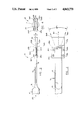
- FIG. 1 is a partially-exploded perspective view of a preferred embodiment of the nozzle of the present invention.
- FIG. 2 is a top view of an assembled nozzle of FIG. 1.
- FIG. 3 is an enlarged, partial side view of the nozzle of FIG. 2.
- FIG. 4 is an end view of the nozzle of FIG. 2.
- a discharge nozzle body 12 includes an inlet portion 14, a throat portion 16, a passageway 18 and an exit 20.
- the cross section of the inlet portion 14 be circular. It is preferred that the cross section of the passageway 18 be rectangular. It is further preferred that the cross section of passageway 18 be flattened and substantially less than the cross section of the inlet portion 14. It is understood that other cross sections and shapes are within the scope of the present invention.
- a pair of deflectors or guide plates 22A and 22B are secured to the flattened passageway 18 adjacent the exit 20.
- the deflectors 22A and 22B can be secured to the passageway 18 in any constraint manner, e.g. by bolts 24A-24D and nuts 26A-26D (26A is not illustrated).
- Bolts 24A-24D are threaded through respective openings 28A-28D and 29A-29D in deflectors 22A and 22B and held in place by nuts 26A-26D, respectively. It is understood that other fasteners can be utilized to secure deflectors 22A and 22B to the passageway 18.
- the deflectors 22A and 22B can be secured to the passageway 18 by welding and the like.
- flanges on the outer surface 18A of the passageway 18 adjacent the exit 20. Fasteners can be inserted through the flanges.
- the deflectors 22A and 22B can be welded or otherwise secured to such flanges.
- a gap 30 remains between the deflectors 22A and 22B beyond exit 20 after the deflectors 22A and 22B have been installed on the passageway 18. It is preferred that gap 30 be substantially equal to the lateral width W of exit 20.
- a stepped surface 32A and 32B is provided on the surface of each deflector 22A and 22B, respectively, adjacent the passageway 18. It is preferred that each stepped surface 32A and 32B be substantially the same width as the thickness of the outer walls of the passageway 18.
- the inlet portion 14 is connected to a source of air or other gases indicated by arrow 33. Air passes through the inlet portion 14, throat 16 and passageway 18 and achieves a sonic velocity due to the reduction in cross-sectional area and by the boundary layer of friction along the length of the inner walls of te passageway 18.
- deflectors 22A and 22B increase the velocity of the exiting gases. Furthermore, the swath of the gases can be broadened to an angle of forty or more degrees.
- the present nozzle 10 is particularly well-suited for use with a cyrogenic cleaning apparatus.
- Carbon dioxide pellets carried by air are directed by deflectors 22A and 22B into a broad swath.
- Such a swath substantially increases the cleaning effectiveness of a nozzle without deflectors 22A and 22B.
- the present nozzle 10 has other applications, e.g. sand blasting. Furthermore, many variations in exit velocity, pellet fan divergence angle, deflector size and spacing, effective working distance as a function of supply pressure are all within the scope of the present invention.
Abstract
Description
Claims (3)
Priority Applications (1)
| Application Number | Priority Date | Filing Date | Title |
|---|---|---|---|
| US07/086,405 US4843770A (en) | 1987-08-17 | 1987-08-17 | Supersonic fan nozzle having a wide exit swath |
Applications Claiming Priority (1)
| Application Number | Priority Date | Filing Date | Title |
|---|---|---|---|
| US07/086,405 US4843770A (en) | 1987-08-17 | 1987-08-17 | Supersonic fan nozzle having a wide exit swath |
Publications (1)
| Publication Number | Publication Date |
|---|---|
| US4843770A true US4843770A (en) | 1989-07-04 |
Family
ID=22198355
Family Applications (1)
| Application Number | Title | Priority Date | Filing Date |
|---|---|---|---|
| US07/086,405 Expired - Fee Related US4843770A (en) | 1987-08-17 | 1987-08-17 | Supersonic fan nozzle having a wide exit swath |
Country Status (1)
| Country | Link |
|---|---|
| US (1) | US4843770A (en) |
Cited By (34)
| Publication number | Priority date | Publication date | Assignee | Title |
|---|---|---|---|---|
| EP0437854A1 (en) * | 1990-01-13 | 1991-07-24 | Taiyo Yuden Co., Ltd. | Atomized thin film forming apparatus |
| US5050805A (en) * | 1989-02-08 | 1991-09-24 | Cold Jet, Inc. | Noise attenuating supersonic nozzle |
| US5107764A (en) * | 1990-02-13 | 1992-04-28 | Baldwin Technology Corporation | Method and apparatus for carbon dioxide cleaning of graphic arts equipment |
| US5265383A (en) * | 1992-11-20 | 1993-11-30 | Church & Dwight Co., Inc. | Fan nozzle |
| USH1379H (en) * | 1991-06-25 | 1994-12-06 | The United States Of America As Represented By The Secretary Of The Air Force | Supersonic fan nozzle for abrasive blasting media |
| US5571335A (en) * | 1991-12-12 | 1996-11-05 | Cold Jet, Inc. | Method for removal of surface coatings |
| US5601478A (en) * | 1994-03-01 | 1997-02-11 | Job Industries Ltd. | Fluidized stream accelerator and pressuiser apparatus |
| US5795214A (en) * | 1997-03-07 | 1998-08-18 | Cold Jet, Inc. | Thrust balanced turn base for the nozzle assembly of an abrasive media blasting system |
| US5904334A (en) * | 1997-03-10 | 1999-05-18 | The Horton Company | Quiet high flow control valve |
| US5957760A (en) * | 1996-03-14 | 1999-09-28 | Kreativ, Inc | Supersonic converging-diverging nozzle for use on biological organisms |
| US6024304A (en) * | 1993-10-22 | 2000-02-15 | Cold Jet, Inc. | Particle feeder |
| US6524172B1 (en) | 2000-09-08 | 2003-02-25 | Cold Jet, Inc. | Particle blast apparatus |
| US6626738B1 (en) | 2002-05-28 | 2003-09-30 | Shank Manufacturing | Performance fan nozzle |
| WO2003089193A1 (en) | 2002-04-17 | 2003-10-30 | Cold Jet, Inc. | Feeder assembly for particle blast system |
| US6726549B2 (en) | 2000-09-08 | 2004-04-27 | Cold Jet, Inc. | Particle blast apparatus |
| US6739529B2 (en) * | 1999-08-06 | 2004-05-25 | Cold Jet, Inc. | Non-metallic particle blasting nozzle with static field dissipation |
| WO2006083890A1 (en) | 2005-01-31 | 2006-08-10 | Cold Jet Llc | Particle blast cleaning apparatus with pressurized container |
| US20080296797A1 (en) * | 2007-05-15 | 2008-12-04 | Cold Jet Llc | Particle blasting method and apparatus therefor |
| US20090156102A1 (en) * | 2007-12-12 | 2009-06-18 | Rivir Michael E | Pivoting hopper for particle blast apparatus |
| US20090193615A1 (en) * | 2008-02-01 | 2009-08-06 | Phuong Taylor Nguyen | Fan nozzle |
| CN101721867A (en) * | 2009-12-29 | 2010-06-09 | 天津水泥工业设计研究院有限公司 | Spray head for plenum pulse cloth bag collector |
| US20100170965A1 (en) * | 2009-01-05 | 2010-07-08 | Cold Jet Llc | Blast Nozzle with Blast Media Fragmenter |
| US20100221989A1 (en) * | 2010-02-24 | 2010-09-02 | Phuong Taylor Nguyen | Fan nozzle |
| WO2013116710A1 (en) | 2012-02-02 | 2013-08-08 | Cold Jet Llc | Apparatus and method for high flow particle blasting without particle storage |
| US20140099869A1 (en) * | 2012-10-05 | 2014-04-10 | Phuong Taylor Nguyen | Fan nozzle |
| US9931639B2 (en) | 2014-01-16 | 2018-04-03 | Cold Jet, Llc | Blast media fragmenter |
| US10315862B2 (en) | 2015-03-06 | 2019-06-11 | Cold Jet, Llc | Particle feeder |
| EP3626395A1 (en) | 2018-04-24 | 2020-03-25 | Cold Jet LLC | Particle blast apparatus |
| WO2021035001A1 (en) | 2019-08-21 | 2021-02-25 | Cold Jet, Llc | Particle blast apparatus |
| WO2021138545A1 (en) | 2019-12-31 | 2021-07-08 | Cold Jet, Llc | Method and apparatus for enhanced blast stream |
| WO2022236041A1 (en) | 2021-05-07 | 2022-11-10 | Cold Jet, Llc | Method and apparatus for forming solid carbon dioxide |
| US11607774B2 (en) | 2015-10-19 | 2023-03-21 | Cold Jet, Llc | Blast media comminutor |
| WO2023158868A1 (en) | 2022-02-21 | 2023-08-24 | Cold Jet, Llc | Method and apparatus for minimizing ice build up within blast nozzle and at exit |
| WO2024006405A1 (en) | 2022-07-01 | 2024-01-04 | Cold Jet, Llc | Method and apparatus with venting or extraction of transport fluid from blast stream |
Citations (8)
| Publication number | Priority date | Publication date | Assignee | Title |
|---|---|---|---|---|
| DE9147C (en) * | ||||
| US1133711A (en) * | 1913-03-20 | 1915-03-30 | Benjamin L Cornelius | Oil-burner tip. |
| US2606073A (en) * | 1949-10-24 | 1952-08-05 | William C Uhri | Washing and cleaning gun |
| US2897692A (en) * | 1955-06-09 | 1959-08-04 | Simonds Saw & Steel Co | Process for file making |
| US3662497A (en) * | 1970-11-02 | 1972-05-16 | Thomas L Thompson | Abrasive motor slot cleaning nozzle |
| US4169556A (en) * | 1976-10-26 | 1979-10-02 | Myers-Europe Gmbh | Flat jet discharge device for a mixture of a pressurized liquid with solid particles |
| US4306684A (en) * | 1979-12-04 | 1981-12-22 | American Can Company | Low noise air nozzle |
| US4641786A (en) * | 1984-12-14 | 1987-02-10 | Cryoblast, Inc. | Nozzle for cryogenic cleaning apparatus |
-
1987
- 1987-08-17 US US07/086,405 patent/US4843770A/en not_active Expired - Fee Related
Patent Citations (8)
| Publication number | Priority date | Publication date | Assignee | Title |
|---|---|---|---|---|
| DE9147C (en) * | ||||
| US1133711A (en) * | 1913-03-20 | 1915-03-30 | Benjamin L Cornelius | Oil-burner tip. |
| US2606073A (en) * | 1949-10-24 | 1952-08-05 | William C Uhri | Washing and cleaning gun |
| US2897692A (en) * | 1955-06-09 | 1959-08-04 | Simonds Saw & Steel Co | Process for file making |
| US3662497A (en) * | 1970-11-02 | 1972-05-16 | Thomas L Thompson | Abrasive motor slot cleaning nozzle |
| US4169556A (en) * | 1976-10-26 | 1979-10-02 | Myers-Europe Gmbh | Flat jet discharge device for a mixture of a pressurized liquid with solid particles |
| US4306684A (en) * | 1979-12-04 | 1981-12-22 | American Can Company | Low noise air nozzle |
| US4641786A (en) * | 1984-12-14 | 1987-02-10 | Cryoblast, Inc. | Nozzle for cryogenic cleaning apparatus |
Cited By (53)
| Publication number | Priority date | Publication date | Assignee | Title |
|---|---|---|---|---|
| US5050805A (en) * | 1989-02-08 | 1991-09-24 | Cold Jet, Inc. | Noise attenuating supersonic nozzle |
| EP0437854A1 (en) * | 1990-01-13 | 1991-07-24 | Taiyo Yuden Co., Ltd. | Atomized thin film forming apparatus |
| US5090360A (en) * | 1990-01-13 | 1992-02-25 | Taiyo Yuden Co., Ltd. | Atomized thin film forming apparatus |
| US5107764A (en) * | 1990-02-13 | 1992-04-28 | Baldwin Technology Corporation | Method and apparatus for carbon dioxide cleaning of graphic arts equipment |
| USH1379H (en) * | 1991-06-25 | 1994-12-06 | The United States Of America As Represented By The Secretary Of The Air Force | Supersonic fan nozzle for abrasive blasting media |
| US5571335A (en) * | 1991-12-12 | 1996-11-05 | Cold Jet, Inc. | Method for removal of surface coatings |
| US5365702A (en) * | 1992-11-20 | 1994-11-22 | Church & Dwight Co., Inc. | Fan nozzle |
| USRE34854E (en) * | 1992-11-20 | 1995-02-14 | Church & Dwight Co., Inc. | Fan nozzle |
| US5265383A (en) * | 1992-11-20 | 1993-11-30 | Church & Dwight Co., Inc. | Fan nozzle |
| US6024304A (en) * | 1993-10-22 | 2000-02-15 | Cold Jet, Inc. | Particle feeder |
| US5601478A (en) * | 1994-03-01 | 1997-02-11 | Job Industries Ltd. | Fluidized stream accelerator and pressuiser apparatus |
| US5681206A (en) * | 1994-03-01 | 1997-10-28 | Mesher; Terry | Method of accelerating fluidized particulate matter |
| US5779523A (en) * | 1994-03-01 | 1998-07-14 | Job Industies, Ltd. | Apparatus for and method for accelerating fluidized particulate matter |
| US6273789B1 (en) | 1996-03-14 | 2001-08-14 | Lasalle Richard Todd | Method of use for supersonic converging-diverging air abrasion nozzle for use on biological organisms |
| US5957760A (en) * | 1996-03-14 | 1999-09-28 | Kreativ, Inc | Supersonic converging-diverging nozzle for use on biological organisms |
| US5795214A (en) * | 1997-03-07 | 1998-08-18 | Cold Jet, Inc. | Thrust balanced turn base for the nozzle assembly of an abrasive media blasting system |
| US5904334A (en) * | 1997-03-10 | 1999-05-18 | The Horton Company | Quiet high flow control valve |
| US6739529B2 (en) * | 1999-08-06 | 2004-05-25 | Cold Jet, Inc. | Non-metallic particle blasting nozzle with static field dissipation |
| US6524172B1 (en) | 2000-09-08 | 2003-02-25 | Cold Jet, Inc. | Particle blast apparatus |
| US6726549B2 (en) | 2000-09-08 | 2004-04-27 | Cold Jet, Inc. | Particle blast apparatus |
| US20040224618A1 (en) * | 2000-09-08 | 2004-11-11 | Rivir Michael E. | Particle blast apparatus |
| US7950984B2 (en) | 2000-09-08 | 2011-05-31 | Cold Jet, Inc. | Particle blast apparatus |
| WO2003089193A1 (en) | 2002-04-17 | 2003-10-30 | Cold Jet, Inc. | Feeder assembly for particle blast system |
| US7112120B2 (en) | 2002-04-17 | 2006-09-26 | Cold Jet Llc | Feeder assembly for particle blast system |
| US20070128988A1 (en) * | 2002-04-17 | 2007-06-07 | Cold Jet, Inc. | Feeder Assembly For Particle Blast System |
| US6626738B1 (en) | 2002-05-28 | 2003-09-30 | Shank Manufacturing | Performance fan nozzle |
| WO2006083890A1 (en) | 2005-01-31 | 2006-08-10 | Cold Jet Llc | Particle blast cleaning apparatus with pressurized container |
| US20080296797A1 (en) * | 2007-05-15 | 2008-12-04 | Cold Jet Llc | Particle blasting method and apparatus therefor |
| US9095956B2 (en) | 2007-05-15 | 2015-08-04 | Cold Jet Llc | Method and apparatus for forming carbon dioxide particles into a block |
| US20090156102A1 (en) * | 2007-12-12 | 2009-06-18 | Rivir Michael E | Pivoting hopper for particle blast apparatus |
| US20090193615A1 (en) * | 2008-02-01 | 2009-08-06 | Phuong Taylor Nguyen | Fan nozzle |
| US20100170965A1 (en) * | 2009-01-05 | 2010-07-08 | Cold Jet Llc | Blast Nozzle with Blast Media Fragmenter |
| US8187057B2 (en) | 2009-01-05 | 2012-05-29 | Cold Jet Llc | Blast nozzle with blast media fragmenter |
| CN101721867A (en) * | 2009-12-29 | 2010-06-09 | 天津水泥工业设计研究院有限公司 | Spray head for plenum pulse cloth bag collector |
| US20100221989A1 (en) * | 2010-02-24 | 2010-09-02 | Phuong Taylor Nguyen | Fan nozzle |
| WO2013116710A1 (en) | 2012-02-02 | 2013-08-08 | Cold Jet Llc | Apparatus and method for high flow particle blasting without particle storage |
| US9592586B2 (en) | 2012-02-02 | 2017-03-14 | Cold Jet Llc | Apparatus and method for high flow particle blasting without particle storage |
| US20140099869A1 (en) * | 2012-10-05 | 2014-04-10 | Phuong Taylor Nguyen | Fan nozzle |
| US9931639B2 (en) | 2014-01-16 | 2018-04-03 | Cold Jet, Llc | Blast media fragmenter |
| US20190291975A1 (en) * | 2015-03-06 | 2019-09-26 | Cold Jet, Llc | Particle feeder |
| US10737890B2 (en) * | 2015-03-06 | 2020-08-11 | Cold Jet, Llc | Particle feeder |
| US10315862B2 (en) | 2015-03-06 | 2019-06-11 | Cold Jet, Llc | Particle feeder |
| US11607774B2 (en) | 2015-10-19 | 2023-03-21 | Cold Jet, Llc | Blast media comminutor |
| US11766760B2 (en) | 2015-10-19 | 2023-09-26 | Cold Jet, Llc | Method of comminuting particles |
| EP3626395A1 (en) | 2018-04-24 | 2020-03-25 | Cold Jet LLC | Particle blast apparatus |
| US11731243B2 (en) | 2018-04-24 | 2023-08-22 | Cold Jet, Llc | Spring return actuator for rotary valves |
| EP4098888A1 (en) | 2018-04-24 | 2022-12-07 | Cold Jet LLC | Particle blast apparatus |
| WO2021035001A1 (en) | 2019-08-21 | 2021-02-25 | Cold Jet, Llc | Particle blast apparatus |
| WO2021138545A1 (en) | 2019-12-31 | 2021-07-08 | Cold Jet, Llc | Method and apparatus for enhanced blast stream |
| US11780051B2 (en) | 2019-12-31 | 2023-10-10 | Cold Jet, Llc | Method and apparatus for enhanced blast stream |
| WO2022236041A1 (en) | 2021-05-07 | 2022-11-10 | Cold Jet, Llc | Method and apparatus for forming solid carbon dioxide |
| WO2023158868A1 (en) | 2022-02-21 | 2023-08-24 | Cold Jet, Llc | Method and apparatus for minimizing ice build up within blast nozzle and at exit |
| WO2024006405A1 (en) | 2022-07-01 | 2024-01-04 | Cold Jet, Llc | Method and apparatus with venting or extraction of transport fluid from blast stream |
Similar Documents
| Publication | Publication Date | Title |
|---|---|---|
| US4843770A (en) | Supersonic fan nozzle having a wide exit swath | |
| US4653693A (en) | Fire fighting fog nozzle | |
| US7036753B2 (en) | Internal mixing atomizing spray nozzle assembly | |
| US5387376A (en) | Process and apparatus for mass transfer between liquid and gaseous media | |
| JP2601031B2 (en) | Fan-shaped nozzle | |
| US5435489A (en) | Engine exhaust gas deflection system | |
| US5402938A (en) | Fluid amplifier with improved operating range using tapered shim | |
| US3954921A (en) | Gas-liquid contacting method and scrubber used therefor | |
| US3510065A (en) | Descaling nozzle | |
| US4456181A (en) | Gas liquid mixing nozzle | |
| US6293857B1 (en) | Blast nozzle | |
| US1889201A (en) | Spray nozzle | |
| US6561440B1 (en) | Full cone spray nozzle for metal casting cooling system | |
| US5382389A (en) | Foam producing venturi and method of using same | |
| US5992529A (en) | Mixing passage in a foam fire fighting nozzle | |
| US5509849A (en) | Blast nozzle for water injection and method of using same for blast cleaning solid surfaces | |
| JPS5939270B2 (en) | Guns that produce jets of particulate matter and fluids | |
| US5423483A (en) | Sootblower | |
| KR860008803A (en) | Powder spraying apparatus and method | |
| US5170946A (en) | Shaped nozzle for high velocity fluid flow | |
| JPH08504673A (en) | Flat jet nozzle for high pressure cleaning equipment | |
| US20090193615A1 (en) | Fan nozzle | |
| JP2724771B2 (en) | Mixing device | |
| CA1040860A (en) | Arrangement for cleaning a conduit | |
| JP2927746B2 (en) | Injection nozzle |
Legal Events
| Date | Code | Title | Description |
|---|---|---|---|
| AS | Assignment |
Owner name: COLD JET, INC., OHIO Free format text: ASSIGNMENT OF ASSIGNORS INTEREST.;ASSIGNORS:CRANE, NEWELL D.;MOORE, DAVID E.;REEL/FRAME:005139/0729 Effective date: 19890802 |
|
| FPAY | Fee payment |
Year of fee payment: 4 |
|
| REMI | Maintenance fee reminder mailed | ||
| LAPS | Lapse for failure to pay maintenance fees | ||
| FP | Lapsed due to failure to pay maintenance fee |
Effective date: 19970709 |
|
| AS | Assignment |
Owner name: SIRROM CAPITAL CORPORATION, TENNESSEE Free format text: SECURITY INTEREST;ASSIGNOR:COLD JET, INC.;REEL/FRAME:009350/0661 Effective date: 19980728 Owner name: LASALLE NATIONAL BANK, ILLINOIS Free format text: SECURITY INTEREST;ASSIGNOR:COLD JET, INC.;REEL/FRAME:009350/0661 Effective date: 19980728 |
|
| STCH | Information on status: patent discontinuation |
Free format text: PATENT EXPIRED DUE TO NONPAYMENT OF MAINTENANCE FEES UNDER 37 CFR 1.362 |