EP0957046A1 - Einwurfschleuse für eingehauste Abfallbehälter - Google Patents
Einwurfschleuse für eingehauste Abfallbehälter Download PDFInfo
- Publication number
- EP0957046A1 EP0957046A1 EP99109064A EP99109064A EP0957046A1 EP 0957046 A1 EP0957046 A1 EP 0957046A1 EP 99109064 A EP99109064 A EP 99109064A EP 99109064 A EP99109064 A EP 99109064A EP 0957046 A1 EP0957046 A1 EP 0957046A1
- Authority
- EP
- European Patent Office
- Prior art keywords
- throw
- lock
- lock according
- trough
- user
- Prior art date
- Legal status (The legal status is an assumption and is not a legal conclusion. Google has not performed a legal analysis and makes no representation as to the accuracy of the status listed.)
- Granted
Links
Images


Classifications
-
- E—FIXED CONSTRUCTIONS
- E04—BUILDING
- E04F—FINISHING WORK ON BUILDINGS, e.g. STAIRS, FLOORS
- E04F17/00—Vertical ducts; Channels, e.g. for drainage
- E04F17/10—Arrangements in buildings for the disposal of refuse
-
- B—PERFORMING OPERATIONS; TRANSPORTING
- B65—CONVEYING; PACKING; STORING; HANDLING THIN OR FILAMENTARY MATERIAL
- B65F—GATHERING OR REMOVAL OF DOMESTIC OR LIKE REFUSE
- B65F1/00—Refuse receptacles; Accessories therefor
- B65F1/10—Refuse receptacles; Accessories therefor with refuse filling means, e.g. air-locks
-
- B—PERFORMING OPERATIONS; TRANSPORTING
- B65—CONVEYING; PACKING; STORING; HANDLING THIN OR FILAMENTARY MATERIAL
- B65F—GATHERING OR REMOVAL OF DOMESTIC OR LIKE REFUSE
- B65F1/00—Refuse receptacles; Accessories therefor
- B65F1/14—Other constructional features; Accessories
- B65F1/1426—Housings, cabinets or enclosures for refuse receptacles
-
- B—PERFORMING OPERATIONS; TRANSPORTING
- B65—CONVEYING; PACKING; STORING; HANDLING THIN OR FILAMENTARY MATERIAL
- B65F—GATHERING OR REMOVAL OF DOMESTIC OR LIKE REFUSE
- B65F2210/00—Equipment of refuse receptacles
- B65F2210/108—Authorization means
-
- B—PERFORMING OPERATIONS; TRANSPORTING
- B65—CONVEYING; PACKING; STORING; HANDLING THIN OR FILAMENTARY MATERIAL
- B65F—GATHERING OR REMOVAL OF DOMESTIC OR LIKE REFUSE
- B65F2210/00—Equipment of refuse receptacles
- B65F2210/128—Data transmitting means
-
- B—PERFORMING OPERATIONS; TRANSPORTING
- B65—CONVEYING; PACKING; STORING; HANDLING THIN OR FILAMENTARY MATERIAL
- B65F—GATHERING OR REMOVAL OF DOMESTIC OR LIKE REFUSE
- B65F2210/00—Equipment of refuse receptacles
- B65F2210/144—Level detecting means
- B65F2210/1443—Electrical
-
- B—PERFORMING OPERATIONS; TRANSPORTING
- B65—CONVEYING; PACKING; STORING; HANDLING THIN OR FILAMENTARY MATERIAL
- B65F—GATHERING OR REMOVAL OF DOMESTIC OR LIKE REFUSE
- B65F2210/00—Equipment of refuse receptacles
- B65F2210/162—Pressing means
Definitions
- the invention relates to a throw-in lock for housing for housing Waste containers according to the preamble of claim 1.
- DE 195 41 010 C1 is a single-chamber throw-in lock for housed litter bin known in the top cover of the housing is arranged and a rotatably mounted, manually operated lock drum with a lock chamber of constant volume, the one Locking mechanism is assigned.
- This locking mechanism can be designed so that it can only be unlocked by users who have a user authorization.
- the locking mechanism can, for example, by a key, a Chip, a magnetic stripe card or other machine-readable Disks are unlocked to allow authorized users to use them the waste container and allow unauthorized users to use it refuse the waste container to dispose of their waste.
- a microprocessor which is coupled to the actuating device of the insertion lock is, the usage data of the user is saved in a user-friendly manner Allow waste disposal billing.
- the object of the invention is a throw-in lock for housing for housing of waste containers to create an improved waste volume detection and -Accounting option for the appropriate waste disposal cost allocation for users.
- lock chambers can each be rotated independently stored lock drums can be formed by means of a hand-held Actuator can be actuated with a rotary mechanism.
- the Lock drums can advantageously be arranged coaxially next to one another be.
- each filling opening with an unlockable Closure cover is closed. Below this cover is depending on Prior use, the trough recess parked on the left or right of a fixed wall.
- An LED display can show the user the lock chamber on the right or instruct on the left, with the right or left locking mechanism locking accordingly is released.
- a user is closing the cap opens and his garbage, for example in the form of a garbage bag, placed in the trough, is the actuating device for the movable one
- the wall forming the plunger is locked, as is the sliding mechanism for the trough.
- the locking of the cover of Lock chamber activated automatically.
- the locks on the caps can be monitored by sensors so that after closing an open Cover a microprocessor a corresponding input signal is communicated, which then generates an output signal which the respective actuating device for the movable wall and for the trough unlocked.
- the moving mechanism can move the movable wall in the lock chamber against the inserted garbage bag until one builds up defined resistance, by which the pressing process ends becomes. In this way, the unused volume of the lock chamber is optimal reduced.
- the throw-in lock can translate the trough trough simultaneously with the wall forming the plunger be moved along by guides.
- this shift the trough is triggered even when the sensor-determined pressing force is reached be so that either the pressing movement of the movable wall and the sliding movement of the trough trough triggered simultaneously or in succession become.
- a lock chamber alternately on one side and on the other side of a middle one Partition wall also becomes a more even distribution of the garbage within brought about of the waste container, which accordingly improved utilization learns what reduces the cost of waste disposal.
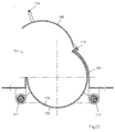
- Fig. 1 is a housing 1 for housing a waste container 2 together with this shown.
- the housing 1 can, for example, be secured against displacement Foundation plate 11 may be connected.
- the waste container 2 is in the open Condition, d. H. with the cover 8 open, in the interior 14 of the Housing 1.
- the waste container 2 is equipped with rollers 12 and can in the interior 14 of the housing 1 by opening the rear wall 13 in and be brought out.
- the upper cover 3 of the housing 1 contains a throw-in lock 4 which can be operated from the front 19 of the housing 1.
- the throw-in lock 4 consists in the embodiment according to FIG. 1 to 5 from at least two lock drums 5.
- a first lock drum 5 has an interior as a lock chamber 6 with an insertion opening 7 and is mounted so as to be rotatable and drivable about its axis of rotation 15.
- the lock chamber 6 is shown in the locked state in the starting position, i.e. it cannot be filled in this angle of rotation position since the insertion opening 7 faces the interior 14 of the housing 1.
- the lock drum 5 has a rotary mechanism 16 which has a Hand lever 10 can be operated as an actuator.
- the lock drum 5 is protected against unauthorized persons by a locking device 17 Use secured.
- the lock drum 5 with its lock chamber 6 is in the open position Position, i.e. shown in an angular position, which is a filling of the Lock chamber 6 allows so that, for example, a trash bag 9 in the Lock chamber 6 can be inserted.
- Fig. 3 shows the enlarged detail X in Fig. 1.
- the lock drum 5 is through the locking device 17 locked.
- the lock drum 5 can of the rotary mechanism 16 are operated.
- This includes a propellant drive For example, a toothed belt drive 20, which from the drive shaft 21 and two toothed belt pulleys 22, 23, which are wrapped by the toothed belt 24 are.
- the rotary mechanism 16 can be operated manually with the hand lever 10, which is rotatably connected to the drive shaft 21, are actuated.
- the on that Housing 1 attached locking device 17 consists of a spring-loaded Incident pawl 25, which is biased by a tension spring 26, the Incident pawl 25 with a locking stop 27 which is rotationally fixed to the drive shaft 21 is connected, is engaged.
- Fig. 4 shows an enlarged detail (Y) of Fig. 2.
- the lock drum (5) is shown in the unlocked state in the open rotational angle position.
- the magnetic plunger 29 actuates the Incident pawl (25) so that it undergoes a rotation through which the locking stop 27 of the drive shaft 21 is released for rotation.
- the locking mechanism 17 can only be unlocked if one preferably system recognition comprising a microprocessor, for example activated via a transponder that interacts with a first input signal generated with the microprocessor, the user in the form of the user ID accepted.
- a microprocessor for example activated via a transponder that interacts with a first input signal generated with the microprocessor, the user in the form of the user ID accepted.
- an initiator 30 for example can be designed as a pushbutton or capacitive proximity switch, activate, which forms a second input signal for the microprocessor, the now generates an output signal which sets the actuator 28 in motion, so that the latch 25 is actuated and the locking device 17 unlocked becomes.
- the output signal for actuating the actuator 28 is time-limited as an input signal fed back to the microprocessor, so that this signal changes into self-holding for a predetermined period of time. After this time has elapsed, the prestressed tension spring 26 is now actuated the incident pawl 25 against the direction of actuation of the magnetic plunger 29, so that the drop latch 25 return to its locking position as the starting position occupies.
- Fig. 5 shows an embodiment for a rotary mechanism 16 for driving the lock drums 5.5 ', 5' 'of a throw-in lock 4, which acts as a three-chamber lock is executed.
- the arrangement of three lock drums is shown 5.5 ', 5' 'with their lock chambers 6.6', 6 '', the axes of rotation 15 one form common axis 18 and which are independent of each other in their bearings 32 are rotatably mounted, which are attached to vertical support walls 31.
- Each of the three lock drums 5.5 ', 5' ' has a different volume Lock chamber 6,6 ', 6' '.
- the gradation of the volumes of the lock chambers 6.6 ', 6' ' can be, for example, 5 liters, 10 liters and 15 liters.
- Each lock chamber 6, 6 ', 6' ' is a hand lever 10, 10', 10 '' with its initiator 30,30 ', 30' 'assigned, with the respective hand lever 10,10', 10 '' Rotating mechanism 16 for the selected lock drum 5.5 ', 5' 'is actuated.
- one of the lock drums becomes activated, i.e. unlocked. This is triggered by operating the hand lift 10,10 ', 10' 'associated initiator 30,30', 30 ''. The input signal triggered thereby enables the microprocessor to register the used ones Lock chamber.
- the user of the multi-chamber insertion lock 4 Depending on the requirements, select the size of the lock chamber 6,6 ', 6' 'that corresponds to the Volume of the garbage bag to be disposed comes closest.
- the rotating mechanism 16 and the locking device 17 is for each of the Lock drums 5.5 ', 5' 'are basically the same as those described above is.
- the drive shafts 21, 21 ', 21' 'with the common axis of rotation 18 stored in the bearings 33,34,35, the drive shafts 21,21 'as hollow shafts are formed so that the drive shaft 21 '', the drive shaft 21 'and both Drive shafts 21 ', 21' 'penetrate the drive shaft 21 in terms of bearings.
- a particular advantage of this embodiment is that the hand lever 10, 10 ', 10' 'of the drive shafts 21, 21', 21 '' is a combined group of juxtaposed hand levers form that are easily accessible and good are manageable.
- the angle of rotation of the Angular movement of the hand lever 10,10 ', 10' 'but only be about 90 ° is the gear ratio between the respective driving pulley 22, 22 ', 22' 'to the driven toothed belt pulley 23 approximately 2: 1.
- the propellant transmission for generating a torque for actuating a Lock drum 5.5, ', 5' 'can be used, for example, as a toothed, wedge, flat belt drive or be designed as a gear transmission.
- the microprocessor's internal switching logic ensures that at all times only a lock drum can be operated.
- the microprocessor can be battery-operated, for example. For special energy-saving operation of the microprocessor can this outside of Activation times are operated in energy-saving mode. This can be special advantageously brought about by using transponder technology be, since the operation of the transponder technology on a very low Energy level based.
- a transponder as an electronic key with a key code is special suitable, with this being assigned a user ID.
- Transponder circuits have a reading module which is inside its Reading area recognizes the user coding of the electronic key, and in the case of the authorized user ID via a read contact a first input signal for activating the control electronics of the Microprocessor generated.
- the user ID can also be encoded, for example Magnetic stripe card or by special key release.
- the microprocessor contains an electronic one, but not in the event of a power failure volatile memory.
- the user ID and the frequency are saved the use of the individual lock chambers related to the date and time. Via an interface of the microprocessor can be freely determined Time intervals, for example monthly, related to the usage data retrieved the user ID for billing waste disposal costs become.
- Another advantage of a multi-chamber lock with different Volumes of the lock chamber is that by using the different lock chambers the scatter, i.e. the distribution of the trash bags within the waste container 2 is favorable and thus its degree of filling or improved the use of space.
- FIG. 6 shows a housing 101 for housing a waste container 102 together with it shown this.
- the housing 101 can be secured against displacement with the foundation plate 111 be connected.
- the waste container 102 is in the open Condition, in the interior 114 of the housing 101.
- the waste container 102 is equipped with rollers 112 and can in the interior 114 of the housing 10 can be moved in and out by opening the rear wall 113.
- the top cover 103 of the housing 101 contains a throw-in lock 104, which can be operated from the front of the housing 101.
- the throw-in lock 104 with its lock chamber 106 exists in this Embodiment of the invention from a lock chamber housing 105 with a closure cap 108, which opens or blocks the filling opening 107, the closure cover 108 about a hinge axis via a handle 116 115 can be folded up.
- the lock chamber housing 105 is advantageous as Prefabricated unit and with the top cover 103 of the housing 101, which has a corresponding opening, screwed.
- the cap 108 is with a locking mechanism, not shown, advantageous the locking mechanism described above corresponding locking mechanism coupled and can only be opened by a user who has access authorization disposes.
- Such a locking mechanism can, for example also be designed as a magnet-operated locking mechanism.
- the throw-in lock 104 comprises a trough trough 110, which is below the closure lid 108 translatable on a prismatic guide 117 is guided and forms a unit with the lock chamber housing 105.
- the throw-in lock 104 is in the open, that is to say unlocked, state shown.
- a garbage bag 109 can thus pass through the filling opening 107 in the lock chamber 106 are inserted.
- Fig. 8 the lock chamber 106 is in the closed state with inserted Garbage bag 109 shown.
- FIG. 10 shows a section of the lock chamber 106 according to detail X in FIG. 6 in an enlarged view.
- the cross section of the lock chamber 106 is formed by the trough 110 with the trough wall 128, the lock chamber housing 105 and the cap 108.
- the cap 108 is hinged about the hinge axis 115 in the hinge bearing 125.
- FIG. 11 shows the section through the opened lock chamber 106 according to the detail Y in Fig. 7 in an enlarged view.
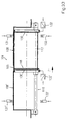
- the housing 12 shows a longitudinal section through the lock chamber housing 105 in parallel and running half the distance to the prism guides 117.
- the housing 105 consists of the two end walls 120, the top cover 121, and the circumferential flange collar 122, with the attached to it Prismatic guides 117. These are, for example, cylindrical rod guides formed, which are clamped at their ends in bearing blocks 123 and are pinned by means of clamping sleeves 124, for example.
- the Lock chamber housing 105 halfway to end walls 120 over a fixed wall 118, this with the lock chamber housing 105 is a unit by a fixed connection. This connection can for example be produced by a welded connection.
- FIG. 13 shows a view in the direction U in FIG. 12
- FIG. 14 shows a bottom view of the lock chamber housing 105 in the direction V in FIG. 12.
- FIG. 14 illustrates the parallel prism guides 117 that are in the pedestals 123 are pinned and stored.
- the circumferential flange collar 122 contains through holes 126 in the long sides for the passage of Screws, which lock chamber housing 105 with the top cover 103 of the housing 101 can be screwed.
- Fig. 15 shows a section along the line A-A in Fig. 12 in an enlarged view.
- the partition 118 is designed so that it is partially between the upper Housing wall 105 and the partition wall 118 releases a gap opening 127, so that the trough trough 110 slide under this fixed partition 118 can. At the same time, the partition 118 prevents the trough 110 from being carried along of the garbage bag 109.
- the trough 110 consists of a trough wall 128, which with the surrounding guides 129 forms a unit, the surrounding guides 129 being designed in this way are that they grip the prism guides 117.
- the front ends the trough wall 128 are open on both sides.
- Fig. 17 shows a section along the line C-C in Fig. 16 and Fig. 18 a lower View in the direction W of the trough 110 in FIG. 17.
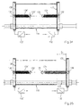
- FIG. 19 illustrates a longitudinal section through a complete throw-in lock 104 with inserted garbage bag 109 with trough recess 110 parked on the right, i.e. to the right of the fixed wall 118, the cover 108 being closed is.
- the displaceable wall 130 serves as a plunger and is located on the right side in the parking position. Is also in a parking position the displaceable wall 130 'as a plunger in the left-hand parking position the trough trough 110. Both closure covers 108, 108 'are closed and locked.
- the trough 110 and the movable walls 130, 130 'become common on the same prismatic guide 117 guided translationally.
- Fig. 20 shows a section along the line D-D in Fig. 19 with inserted garbage bag 109 and FIG. 21 a view of the insertion lock from below in the direction V in Fig. 19.
- the cause of the upsetting is the pressing force (P) as the action force, which is opposed by the reaction force (-P) which emanates from the fixed wall 118.
- the original chamber volume of the lock chamber 106 has now been reduced to the remaining lock chamber volume 106 '.
- the distance ( ⁇ S) multiplied by the cross section of the lock chamber represents the remaining chamber volume, which at the same time forms the chamber volume to be billed for the user.
- the reduction in the chamber volume is brought about by displacing the movable wall 130 as a press piston by the displacement path (S 1 ).
- the displacement path (S 1 ) is reported by a displacement sensor 132 to a microprocessor, which stores it as a value.
- the force (P) with which the displaceable wall 130 acts on the garbage bag 109 is detected by means of a sensor, for example designed as a load cell, and is likewise reported to the microprocessor. When the preselected setpoint, which is stored in the microprocessor, is reached, the displacement movement of the displaceable wall 130 as a plunger is stopped.
- Fig. 23 shows a section along the line D-D in Fig. 17 and Fig. 24 is a view from below in the direction V in FIG. 22.
- FIG. 25 shows a longitudinal section through the throw-in lock 104 analogous to FIG. 22, the displaceable wall 130 remaining in its position with the displacement path (F 1 ) according to FIG. 19.
- the trough trough 110 has covered a further displacement path and overall the displacement path (S 2 ) and has thus simultaneously reached its left parking position. It is thus on the left side of the movable wall 130 'as a plunger.
- Fig. 26 shows a section along the line D-D in Fig. 25 and Fig. 27 is a view in the direction V in Fig. 25 from below.
- FIG. 29 shows a longitudinal section through the insertion lock 104, whereby the trough 110 is in the left parking position and the sliding Wall 130 as a plunger is again on the right side in its starting position located.
- the clamping force P of the garbage bag 109 is eliminated, so that the garbage bag 109 follows the passage opening 126 by gravity could happen and is inside the waste container 102.
- Fig. 29 shows a section along the line D-D in Fig. 28 and Fig. 30 is a view in the direction V in Fig. 28 from below.
- FIG. 31 shows the starting position for the repetition analogously to FIG. 28 of the filling process on the left.
- the lock chamber 106 below the closure cover 108 '.
- Both Caps 108,108 ' are locked in this park position, which is a microprocessor is reported by the sensors 131, 131 'as input signals.
- the respective parking position of the trough depression 110 can be determined via the sensors 133, 133 ' also be reported to the microprocessor as an input signal, so that the An LED display lets users identify which side the feed lock can be released for use.
- the moveable Walls 130, 130 ' are each equipped with a sensor as a displacement sensor 132.132 '.
- FIG. 32 shows a longitudinal section through a throw-in lock 104, wherein 19, a garbage bag 109 is located in the lock chamber 106 'as in FIG. 19.
- the emptying process can be carried out in the same order as in the 19 to 30 shown take place, the direction of movement of the trough 110 then follows the direction arrow with the direction of movement F '.
- This coupling can for example by tension springs or by controlled pneumatic cylinders or be realized by a combination of tension springs and pneumatic cylinders.
- Fig. 33 shows a longitudinal section through a throw-in lock 104 with left and on the right-hand side of the trough trough 110 coupled to the sliding walls 130.130 '.
- FIG. 34 shows an enlarged illustration of the trough depression 110 according to FIG. 33 with a coupling which is generated by the tension springs 134, 134 '.
- the tension springs 134, 134 ' are on the one hand on both sides of the trough trough 110 in the attachment points 135.135 'and on the other hand on the movable walls 130.130' in the anchor points 136, 136 'struck and pretensioned so that the movable Walls 130, 130 'with the prestressed force of the tension springs 134, 134 'can be pressed against the front openings of the trough trough 110.
- FIG. 35 finally shows the trough trough 110 according to FIG. 34 with the wall 130 displaced relative to the trough trough 110, so that it opens a passage opening 119 downward, for example through the displacement path (S 3 ).
- This presupposes that the displaceable wall 130 can be displaced by an actuating element, for example a pneumatic cylinder, against the spring force of the tension spring 134, so that the passage opening 119 is continuous but limited by the trough depression 110 during the displacement movement (F or F ') can increase the stroke of the pneumatic cylinder.
- the passage cross section of the passage opening 119 can be brought about in a controlled manner, which is required in order, for example, to drop a garbage bag 109 into the waste container 2.
- FIGS. 36 and 37 show a further embodiment in analogy to FIGS. 34 and 35 a trough 110 with the sliding wall 130 with a Coupling by leaf springs 137.
- a leaf spring 137 is designed so that it a bend 138 at one end and screw connections at the other end 139 for attachment to the trough trough 110.
- the crank 138 is for example, V-shaped, so that the offset 138 is on both sides Bevel.
- the offset 138 engages behind in the direction of displacement the sliding wall 130 on it and thereby creates during the sliding movement F of the trough 110 a positive and positive connection between the leaf spring 137 and the slidable wall 130.
- the section modulus of the leaf spring is dimensioned so that the Leaf spring 137 against evasion, i.e. against their deformation due to bending, is opposed to a clamping force counteracting the deformation, so that of this leaf spring 137 a towing force to take the displaceable Wall 130, 130 'goes out.
- the transport movement of the trough 110 and the displaceable Wall 130 brought about by the drive by means of an electric motor for example by combining the drive elements, toothed pinion - rack or drive spindle - spindle nut or drive wheel - drive belt, so increases during the impact of the sliding wall 130 on the Obstacle garbage, for example a garbage bag 109, the drive torque required on the output shaft of the electric motor, which simultaneously with an increase in its current consumption is connected.
- the current consumption threshold is exceeded when this current consumption is exceeded this event as the beginning of the standstill of the sliding wall 130, which is fed to the microprocessor as an input signal.
- Waste disposal volume can be determined and saved.
- Travel sensor 132 132 'can also be designed, for example, as an incremental encoder be coupled to the output shaft of the electric motor.
- An alternative embodiment of a towing mechanism for leaf spring design 36 or FIG. 37 can also by a magnetic contact between the trough trough 110 and the displaceable wall 130, 130 ' the drag force represents the magnetic holding force. After exceeding the magnetic holding force, the towing force is interrupted, like already described above.
- the magnetic holding force can be optional generated either by a permanent magnet or by an electromagnet become.
- microprocessor control 149 an embodiment of an actuator 147 of a garbage throw with a spindle drive.
- the system structure of the microprocessor control is structurally essentially characterized by the functional units User interface 150, measuring, control, control electronics (MSR electronics or microprocessor) 151, parameter calculation 152, user data memory 153 and external interface 154.
- MSR electronics or microprocessor control electronics
- the sensors of the microprocessor control 149 consist of an incremental encoder 144 as a displacement transducer, for example equipped with an impulse sensor Hall sensor, a current consumption sensor 148 and the end position sensors 159; 159 '.
- the reference sensor is used to reference the displacement transducer 160, which is assigned to a defined starting position of the trough depression 110 is.
- the reference sensor 160 is the MSR electronics 151 as an input signal E 160 is assigned.
- the drive spindle serves as the drive element of the actuating device 147 140, for example designed as a ball screw, which is provided by an electric motor 143 is powered by the battery 155 as a power supply.
- the drive spindle 140 is in their spindle bearings 141, which on the lock chamber housing 105 are supported, stored.
- the drive shaft 145 of the electric motor 143 and the drive spindle 140 are rotationally fixed by means of a coupling 146 coupled.
- the housing of the electric motor 143 is also on the lock chamber housing 105 supported thereby also the reaction torque of the drive torque is supported against the lock chamber housing 105.
- the trough trough 110 is connected to the drive spindle by means of a spindle nut 142 140 slidably coupled.
- a spindle nut 142 140 slidably coupled.
- the Drive spindle 140 shown below the trough trough 110, the drive spindle 140 because of the falling garbage outside the throw-in area the trough trough 110 must be placed parallel to the movement movement F.
- the user interface 150 consists of a reading module for recognizing the user authorization, for example designed as an electronic key according to the transponder technology. With the transponder 157 as electronic With appropriate user identification, the throw-in lock 104 can be key activated, i.e. unlocked for use so that one of the caps 108,108 'unlocked depending on the parking position of the trough trough 110 becomes.
- the garbage can for example a garbage bag 109, inserted into the lock chamber 106, 106 ' become.
- the MSR electronics 149 generates an output signal A156 or A156 ', which defines the direction of rotation of the electric motor 143 and this thereby being set in motion. This also makes the shifting movement the trough trough 110 including the respectively associated displaceable Wall 130, 130 'started.
- the drive shaft of the electric motor 143 stands with an incremental encoder 144 in operative connection, so that the incremental encoder 144 as a displacement sensor for the current determination of the location coordinate along the displacement path in relation acts on the reference point of the trough trough 110.
- the incremental encoder pulses 144 are present as input signal E 144 at the MSR electronics 151, so that the parameter calculation 152 the current location coordinate of the Trough depression 110 with respect to the reference point of the reference sensor 160 during the travel of the trough 110 is known.
- the circuit of the electric motor 143 is with a current consumption sensor 148 equipped, which detects the current power consumption.
- the current collector generates the input signal E148 on the MCR electronics.
- the path coordinate of the trough depression during the arrival of this event is also known as input signal E144, can by the parameter calculation 152, assigned to the respective user, the claimed Waste disposal volume is stored in the user data storage 153 become.
- the user data is stored in a RAM memory.
- a RAM memory This can for example, be designed as an EPROM memory or as a chip card (Data storage card).
- the data memory can also be used as RAM memory be formed, the stored data via an external interface 154 can be transferred to external data storage. This can for example also by radio transmission using a transmitter 158.
- Another advantage of the invention is that the systematic Recording and storage of the waste disposal volume used by adding up the waste disposal volume, the degree of filling of the waste container can be continuously determined. This makes a separate one unnecessary Fill level control, especially considering statistical Evaluations of an almost completely filled waste container is recognized in good time, which causes possible blockages and thus malfunctions of the operational process can be prevented by the access authorization is blocked in time. An indication of this condition can also be given in time Clues. This can be sent to a waste disposal company via a radio link be communicated, causing the waste container to be emptied can.
Abstract
Description
- Fig. 1
- ein Gehäuse zur Einhausung mit einem darin befindlichen Abfallbehälter,
- Fig. 2
- die Schleusenkammer in geöffneter, d. h. befüllbarer Stellung,
- Fig. 3
- das Detail (X) in Fig. 1, in Vergrößerung,
- Fig. 4
- das Detail (Y) in Fig. 2, in Vergrößerung,
- Fig. 5
- einen Drehmechanismus zur Betätigung verschiedener Schleusentrommeln der Einwurfschleuse gemäß Schnitt A-A in Fig. 4,
- Fig. 6
- ein Einhausungsgehäuse mit darin befindlichem Abfallbehälter und einer Einwurfschleuse in einer abgewandelten Ausführung,
- Fig. 7
- die Einwurfschleuse gemäß Fig. 6 in entriegelter, d.h. freigegebener und geöffneter Stellung,
- Fig. 8
- die Einwurfschleuse gemäß Fig. 6 in geschlossener Stellung mit eingelegtem Müllbeutel,
- Fig. 9
- die Einwurfschleuse in nach unten offener Entleerungsstellung,
- Fig. 10
- einen Schnitt durch die Schleusenkammer der Einwurfschleuse gemäß Einzelheit X in Fig. 6 in vergrößerter Darstellung,
- Fig. 11
- einen Schnitt durch die geöffnete Schleusenkammer gemäß Einzelheit Y in Fig. 7,
- Fig. 12
- einen Längsschnitt durch das Schleusenkammergehäuse parallel und im halben Abstand zu den Prismenführungen verlaufend,
- Fig. 13
- eine Ansicht in Richtung U in Fig. 12,
- Fig. 14
- eine Ansicht in Richtung V in Fig. 12,
- Fig. 15
- einen Schnitt nach der Linie A-A in Fig. 12 in vergrößerter Darstellung,
- Fig. 16
- einen Querschnitt durch eine Trogmulde der Einwurfschleuse nach Fig. 6,
- Fig. 17
- einen Schnitt nach der Linie C-C in Fig. 16,
- Fig. 18
- eine Ansicht der Trogmulde in Richtung W in Fig. 17,
- Fig. 19
- einen Längsschnitt durch eine komplette Einwurfschleuse mit eingelegtem Müllbeutel mit rechtsseitig geparkter Trogmulde,
- Fig. 20
- einen Schnitt nach der Linie D-D in Fig. 19 mit eingelegtem Müllbeutel,
- Fig. 21
- eine Ansicht der Einwurfschleuse in Richtung V in Fig. 19,
- Fig. 22
- einen Längsschnitt durch eine komplette Einwurfschleuse mit eingelegtem Müllbeutel in verpresstem Zustand,
- Fig. 23
- einen Schnitt nach der Linie D-D in Fig. 17,
- Fig. 24
- eine Ansicht der Einwurfschleuse in Richtung V in Fig. 22,
- Fig. 25
- einen Längsschnitt durch eine komplette Einwurfschleuse mit eingelegtem Müllbeutel im verpressten Zustand mit Trogmulde in linker Anschlagposition,
- Fig. 26
- einen Schnitt nach der Linie D-D in Fig. 25,
- Fig. 27
- eine Ansicht der Einwurfschleuse in Richtung V in Fig. 20,
- Fig. 28
- einen Längsschnitt durch eine komplette Einwurfschleuse analog zu Fig. 25, nachdem der Müllbeutel durch Zurückfahren der beweglichen Wand in den Abfallbehälter gefallen ist,
- Fig. 29
- einen Schnitt nach der Linie D-D in Fig. 28,.
- Fig. 30
- eine Ansicht der Einwurfschleuse in Richtung V in Fig. 23,
- Fig. 31
- eine Ansicht der Einwurfschleuse in Ausgangsstellung für die Wiederholung des Beschickungsvorganges analog zu Fig. 28 mit linksseitig geparkter Trogmulde,
- Fig. 32
- einen Längsschnitt durch die Einwurfschleuse gemäß Fig. 6 mit eingelegtem Müllbeutel mit linksseitig geparkter Trogmulde,
- Fig. 33
- einen Längsschnitt durch die Einwurfschleuse mit links- und rechtsseitig der Trogmulde an dieser angekoppelten, verschiebbaren Wänden,
- Fig. 34
- vergrößerte Darstellung der Trogmulde gemäß Fig. 33 mit Zugfederankopplung,
- Fig. 35
- eine Ansicht der Trogmulde gemäß Fig. 34 mit relativ zur Trogmulde verschobener Wand.
- Fig. 36
- vergrößerte Darstellung der Trogmulde gemäß Fig. 33 mit Blattfederankopplung,
- Fig. 37
- eine Ansicht der Trogmulde gemäß Fig. 36 mit relativ zur Trogmulde verschobener Wand.
- Fig. 38
- prinzipieller Aufbau einer Mikroprozessorsteuerung an einem Ausführungsbeispiel einer Betätigungseinrichtung einer Mülleinwurfschleuse am Beispiel eines Spindelantriebs
Claims (54)
- Einwurfschleuse für Gehäuse (1) zur Einhausung von Abfallbehältern (2), mit einer durch eine Einwurföffnung mit Abfall, z.B. Müllbeuteln, beschickbaren und in den Abfallbehälter (2) entleerbaren, aus einer Befüllungsstellung in eine Entleerungsstellung bewegbaren Schleusenkammer dadurch gekennzeichnet, daß die Einwurfschleuse (4;104) einem Benutzer Schleusenkammern (6,6',6'';106) mit unterschiedlichen Kammervolumen darbietet.
- Einwurfschleuse nach Anspruch 1, dadurch gekennzeichnet, daß die Einwurfschleuse mehrere, getrennte Schleusenkammern (6,6',6'') aufweist, die voneinander verschiedene Kammervolumen haben.
- Einwurfschleuse nach einem der Ansprüche 1 und 2, dadurch gekennzeichnet, daß die Schleusenkammern (6,6',6'') jeweils in einer unabhängig drehbar gelagerten Schleusentrommel (5,5',5'') ausgebildet sind, die mittels einer handgeführten Betätigungseinrichtung mit einem Drehmechanismus (16) betätigbar sind.
- Einwurfschleuse nach Anspruch 3, dadurch gekennzeichnet, daß der Drehmechanismus (16) mit einer Verriegelungseinrichtung (17) ausgestattet ist, die mittels eines maschinenlesbaren Datenträgers entriegelbar und zur Benutzung freigebbar ist.
- Einwurfschleuse nach Anspruch 3 oder 4, dadurch gekennzeichnet, daß jede Schleusenkammer (6,6',6'') mit einer separaten Betätigungseinrichtung separat betätigbar ist und jede Betätigungseinrichtung mit einer ihr zugeordneten separaten Verriegelungseinrichtung (17) versehen ist.
- Einwurfschleuse nach einem der Ansprüche 1 bis 5, dadurch gekennzeichnet, daß die Verriegelungseinrichtung (17) über eine maschinenlesbare Benutzerberechtigung entriegelbar ist.
- Einwurfschleuse nach einem der Ansprüche 1 bis 6, dadurch gekennzeichnet, daß die Verriegelungseinrichtung (17) über eine maschinenlesbare Benutzerkennung und Benutzerberechtigung entriegelbar ist.
- Einwurfschleuse nach einem der Ansprüche 1 bis 7, dadurch gekennzeichnet, daß eine Mikroprozessorsteuerung (149) vorgesehen ist, die die Benutzerkennung und -berechtigung erfassen und auswerten kann und bei festgestellter Benutzerberechtigung ein Ausgangssignal erzeugt, das zur Freigabe der Benutzung der Schleusenkammern (6,6',6,'') der Mikroprozessorsteuerung (149) als erstes Eingangssignal für eine Entriegelung der Verriegelungsmechanismen (17) dient.
- Einwurfschleuse nach einem der Ansprüche 1 bis 8, dadurch gekennzeichnet, daß durch Betätigung eines Initiators (30,30',30''), der dem jeweiligen Drehmechanismus (16) der jeweiligen Schleusentrommel (5,5',5'') zugeordnet ist, ein zweites Eingangssignal für die Mikroprozessorsteuerung (149) erzeugbar ist, das die Entriegelung des Verriegelungsmechanismus (17) einer der Schleusentrommeln (5,5',5'') auslöst.
- Einwurfschleuse nach Anspruch 9, dadurch gekennzeichnet, daß der Initiator (30,30',30'') Bestandteil eines Handhebeis (10,10',10'') zur Betätigung einer Schleusentrommel (5,5',5'') ist.
- Einwurfschleuse nach Anspruch 2 bis 10, dadurch gekennzeichnet, daß die Verriegelungsmechanismen (17) der verschiedenen Schleusentrommeln (5,5',5'') gegen gleichzeitige Betätigung verriegelt sind und jeweils nur ein Verriegelungsmechanismus (17) einer Schleusentrommel (5,5',5'') zur Betätigung freigebbar ist.
- Einwurfschleuse nach einem der Ansprüche 8 bis 11, dadurch gekennzeichnet, daß durch die Betätigung eines der den jeweiligen Drehmechanismen der Schleusentrommeln (5,5',5'') zugeordneten Initiatoren (30,30',30'') der Mikroprozessorsteuerung (149) die Größe des zugehörigen Volumens der Schleusenkammer (6,6',6'') erkennt und diese der Benutzerkennung zuordnet und speichert.
- Einwurfschleuse nach einem der Ansprüche 8 bis 12, dadurch gekennzeichnet, daß die Mikroprozessorsteuerung (149) ausgelöst durch Eingangssignale der Initiatoren (30,30',30'') die Häufigkeit der Benutzung der verschiedenen Schleusenkammern (6,6,6'') datums- und uhrzeitbezogen erfaßt, diese der Benutzerkennung zuordnet und diese Benutzungsdaten insgesamt in einem nichtflüchtigen Speicher abspeichert.
- Einwurfschleuse nach einem der Ansprüche 8 bis 13, dadurch gekennzeichnet, daß die Mikroprozessorsteuerung (149) über eine Schnittstelle verfügt, über die die gespeicherten Benutzerdaten auf einen maschinell lesbaren externen Datenträger übertragbar sind.
- Einwurfschleuse nach einem der Ansprüche 8 bis 14, dadurch gekennzeichnet, daß die Benutzungsfreigabe durch einen elektronischen, auf der Transpondertechnologie basierenden Schlüssel erfolgt.
- Einwurfschleuse nach Anspruch 15, dadurch gekennzeichnet, daß ein Transponder einen Schlüsselcode besitzt, der von dem stationären elektronischen Empfangsteil des Lesemoduls des Transponders innerhalb seines Lesebereichs erfaßt und gelesen werden kann, wobei das Lesemodul mit einem Read-Kontakt verbunden ist, der im Falle einer zugelassenen Benutzerkennung die Steuerungselektronik der Mikroprozessorsteuerung (149) aktiviert.
- Einwurfschleuse nach einem der Ansprüche 1 bis 16, dadurch gekennzeichnet, daß Antriebswellen (21,21',21'') als Bestandteil des Drehmechanismus (16) zur Betätigung der Schleusentrommeln (5,5',5'') vorgesehen sind, die eine gemeinsame Drehachse (18) bilden, wobei einige Antriebswellen (21,21') als Hohlwellen ausgebildet sind.
- Einwurfschfeuse nach Anspruch 17, dadurch gekennzeichnet, daß die Antriebswellen (21,21',21'') sich in ihrer Längserstreckung teilweise durchdringen und die Handhebel (10,10',10''), die drehfest mit der ihnen jeweils zugeordneten Antriebswelle (21,21',21'') verbunden sind, eine zusammengefaßte Gruppe von nebeneinander angeordneten Handhebeln bilden.
- Einwurfschleuse nach Anspruch 17 oder 18, dadurch gekennzeichnet, daß die Antriebswellen (21,21',21'') mit einem Treibmittelgetriebe bestückt sind, das ein durch die Betätigung der Handhebel (10,10'10'') hervorgerufenes Drehmoment auf die Schleusentrommeln (5,5',5'') überträgt.
- Einwurfschleuse nach Anspruch 19, dadurch gekennzeichnet, daß das Treibmittelgetriebe als Zahn- Keil- oder Flachriementrieb oder als Zahnradgetriebe ausgebildet ist.
- Einwurfschleuse nach Anspruch 1 bis 15, dadurch gekennzeichnet, daß die Treibmittelgetriebe ein Übersetzungsverhältnis haben, das dem Drehwinkel der Handhebel (10,10',10'') einen größeren Drehwinkel der Schleusentrommel (5,5',5'') vorgibt.
- Einwurfschleuse nach Anspruch 1, dadurch gekennzeichnet, daß die Einwurfschleuse (104) eine einzige in ihrem Kammervolumen veränderbare Schleusenkammer (106) aufweist.
- Einwurfschleuse nach Anspruch 22, dadurch gekennzeichnet, daß die Schleusenkammer (106) in ihrem Kammervolumen selbsttätig stufenlos dem zu entsorgenden Müllvolumen anpaßbar ist.
- Einwurfschleuse nach Anspruch 22 oder 23, dadurch gekennzeichnet , daß die Schleusenkammer (106) mindestens eine verschiebbare Wand (130,130') aufweist, welche kraftbetätigt relativ zu den übrigen Begrenzungswänden der Schleusenkammer (106) über einen Verschiebeweg (S1) verschiebbar ist.
- Einwurfschleuse nach Anspruch 24, dadurch gekennzeichnet, daß die verschiebbare Wand (130,130') als Presskolben ausgebildet ist, durch den Müll durch eine vorgegebene Presskraft (P) verpreß- und gegebenenfalls deformierbar ist.
- Einwurfschleuse nach Anspruch 24 oder 25, dadurch gekennzeichnet , daß der Verschiebeweg (S1) der verschiebbaren Wand (130) durch einen Wegaufnehmer (132) erfaß- und speicherbar ist.
- Einwurfschleuse nach einem der Ansprüche 24 bis 26, dadurch gekennzeichnet , daß eine feststehende, Teil des Schleusenkammergehäuses (105) bildende Wand (118) der verschiebbaren Wand (130,130') als Widerlager zur Aufnahme deren Presskraft (P) zugeordnet ist.
- Einwurfschleuse nach einem der Ansprüche 22 bis 27, dadurch gekennzeichnet , daß ein Teil der Begrenzungswände der Schleusenkammer (106) als Trogmulde (110) ausgebildet ist, welche translatorisch längs einer Bestandteil des Schleusenkammergehäuses (105) bildenden Führung verschiebbar ist.
- Einwurfschleuse nach einem der Ansprüche 24 bis 28, dadurch gekennzeichnet , daß die Betätigungseinrichtung (147) der verschiebbaren Wand (130,130') und der Trogmulde (110) unmittelbar von Hand betätigbar ist.
- Einwurfschleuse nach einem der Ansprüche 24 bis 28, dadurch gekennzeichnet , daß die Betätigungseinrichtung (147) der verschiebbaren Wand (130,130') und der Trogmulde (110) mittels Hilfsenergie motorisch angetrieben ist.
- Einwurfschleuse nach einem der Ansprüche 24 bis 30, dadurch gekennzeichnet , daß die Trogmulde (110) durch ihre Verschiebbarkeit beidseitig einer feststehenden Wand (118) in Parkpositionen überführbar ist, welche die Befüllstellungen der Trogmulde (110) bilden, wobei in jeder Parkposition die Einwurfschleuse (104) mit einer durch Verschlußdeckel (108,108') verschließ- und verriegelbaren Einfüllöffnung (107,107') versehen ist.
- Einwurfschleuse nach Anspruch 31, dadurch gekennzeichnet , daß eine LED-Anzeige vorgesehen ist, die dem Benutzer die jeweilige Parkposition und damit die für die Benutzung zur Verfügung stehende Einfüllöffnung (107,107') optisch anzeigt.
- Einwurfschleuse nach einem der Ansprüche 22 bis 32, dadurch gekennzeichnet, daß die Einwurfschleuse (104) mit einem mikroprozessorgesteuerten Verriegelungsmechanismus versehen ist, der mittels eines maschinenlesbaren Datenträgers zur Benutzungsfreigabe entriegelbar ist, wobei die Benutzerkenndaten und das in Anspruch genommene Volumen der Schleusenkammer datums- und uhrzeitbezogen von der Mikroprozessorsteuerung (149) erfaß- und abrufbar speicherbar sind.
- Einwurfschleuse nach Anspruch 33, dadurch gekennzeichnet, daß der Verriegelungsmechanismus zur Freigabe der Benutzung der Einwurfschleuse (104) über eine maschinenlesbare Benutzererkennung und/oder Benutzerberechtigung entriegelbar ist.
- Einwurfschleuse nach Anspruch 32 oder 34, dadurch gekennzeichnet, daß die Einwurfschleuse (104) mit einer Mikroprozessorsteuerung (149) ausgestattet ist, die die Benutzererkennung und -berechtigung erfassen, erkennen und speichern kann, wodurch im Falle festgestellter Benutzerberechtigung ein Ausgangssignal erzeugt wird, welches zur Freigabe der Entriegelung des Verriegelungsmechanismus der Einwurfschleuse (104) genutzt wird.
- Einwurfschleuse nach einem der Ansprüche 22 bis 35, dadurch gekennzeichnet, daß die Schleusenkammer (106) durch Verschlußdeckel (108,108') verschlossen und ein Sensor (130,131') vorgesehen ist, der nach Öffnen und anschließendem Schließen einer der Verschlußdeckel (108,108') ein Eingangssignal für die Mikroprozessorsteuerung (149) erzeugt, wodurch ein Ausgangssignal erzeugt wird, welches die Betätigungseinrichtung (147) ingang setzt.
- Einwurfschleuse nach einem der Ansprüche 24 bis 36, dadurch gekennzeichnet, daß den verschiebbaren Wänden (130,130') Wegaufnehmer (132,132',144) zugeordnet sind derart, daß deren Meßdaten der Mikroprozessorsteuerung (149) zur Ermittlung des in Anspruch genommenen Schleusenkammervolumens dienen, wobei dieses Ergebnis abrufbar speicherbar ist.
- Einwurfschleuse nach einem der Ansprüche 32 bis 37, dadurch gekennzeichnet, daß die Mikroprozessorsteuerung (149) über eine Schnittstelle für eine Übertragung gespeicherter Benutzerdaten auf einen maschinell lesbaren externen Datenträger verfügt.
- Einwurfschleuse nach einem der Ansprüche 32 bis 38, dadurch gekennzeichnet, daß zur Benutzungsfreigabe ein elektronischer auf der Transponder-Technologie basierender Schlüssel vorgesehen ist, wobei der Transponder einen Schlüsselcode besitzt, der von dem stationären elektronischen Empfangsteil des Lesemoduls des Transponders erfaß- und lesbar ist, und wobei das Lesemodul mit einem Read-Kontakt im Falle festgestellter Benutzerberechtigung die Steuerungselektronik der Mikroprozessorsteuerung (149) aktiviert.
- Einwurfschleuse nach Anspruch 30, dadurch gekennzeichnet, daß die Betätigungseinrichtung der Trogmulde (110) aus einem Antrieb bestehend aus Elektromotor und Zahnritzel mit Zahnstange besteht.
- Einwurfschleuse nach Anspruch 30, dadurch gekennzeichnet, daß die Betätigungseinrichtung der Trogmulde (110) aus einem Antrieb bestehend aus Elektromotor und Antriebsspindel mit Spindelmutter besteht.
- Einwurfschleuse nach Anspruch 30, dadurch gekennzeichnet, daß die Betätigungseinrichtung der Trogmulde (110) aus einem Antrieb bestehend aus Elektromotor und Treibrad mit Treibriemen besteht.
- Einwurfschleuse nach einem oder mehreren der Ansprüche 22 bis 41, dadurch gekennzeichnet, daß die Welle des Antriebsmotors der Betätigungseinrichtung der Trogmulde (110) mit einem Wegaufnehmer gekoppelt ist.
- Einwurfschleuse nach einem oder mehreren der Ansprüche 40 bis 43, dadurch gekennzeichnet, daß die Stromaufnahme des Antriebsmotors als Elektromotor (143) sensorisch mit einem Stromaufnahmesensors (148) erfaßbar ist, wodurch das Auftreffen der verschiebbaren Wand (130,130') auf den Müll bzw. Müllbeutel (109) als Stromanstieg erkennbar ist, wodurch dieses der Mikroprozessorsteuerung (149) als Eingangssignal (E148) zugeführt wird und die Mikroprozessorsteuerung (149) dieses Eingangssignal (E148) in Verbindung mit einem weiteren Eingangssignal (E144) ausgehend von einem Wegaufnehmer, beispielsweise ausgebildet als Inkrementalgeber (144), zur Ermittlung des in Anspruch genommenen Schleusenkammervolumens heranzieht.
- Einwurfschleuse nach einem oder mehreren der Ansprüche 22 bis 44, dadurch gekennzeichnet, daß die Trogmulde (110) und verschiebbare Wand (130,130') durch Federelemente koppelbar sind.
- Einwurfschleuse nach Anspruch 45, dadurch gekennzeichnet, daß die Federelemente als Blattfedern (137) ausgebildet sind.
- Einwurfschleuse nach einem oder mehreren der Ansprüche 22 bis 44, dadurch gekennzeichnet, daß die Trogmulde (110) und verschiebbare Wand (130,130') durch Magnetkräfte kraftschlüssig koppelbar sind.
- Einwurfschleuse nach einem oder mehreren der Ansprüche 1 bis 47, dadurch gekennzeichnet, daß die Datenübergabe von der stationären Müllcontainereinhausung (1,101) zur weiteren Verarbeitung an externe Datenlesegeräte durch eine Chipkarte (Datenspeicherkarte) erfolgen kann.
- Einwurfschleuse nach einem oder mehreren der Ansprüche 1 bis 46, dadurch gekennzeichnet, daß die Datenübergabe von der stationären Müllcontainereinhausung (1,101) zur weiteren Verarbeitung an externe Datenlesegeräte durch Funkübertragung erfolgen kann.
- Einwurfschleuse nach einem oder mehreren der Ansprüch 1 bis 49, dadurch gekennzeichnet, daß der Befüllungsgrad eines Abfallbehälters (2,102) durch Aufsummierung der tatsächlich in Anspruch genommenen Müllvolumen der Benutzer ermittelt wird.
- Einwurfschleuse nach Anspruch 50, dadurch gekennzeichnet, daß die Einwurfschleuse der Einhausung über eine Verriegelungseinrichtung verfügt, welche die Einwurfschleuse gegen Benutzung sperrt, sobald ein vorgegebener Endbefüllungsgrad als Vollmeldung erreicht ist.
- Einwurfschleuse nach Anspruch 51, dadurch gekennzeichnet, daß die Einwurfschleuse der Einhausung über eine optische Signaleinrichtung verfügt, welche den erreichten Endbefüllungsgrad als Vollmeldung anzeigt.
- Einwurfschleuse nach Anspruch 52, dadurch gekennzeichnet, daß die Einwurfschleuse der Einhausung über eine Signaleinrichtung verfügt, welche mittels eines Funksignals den erreichten Endbefüllungsgrad als Vollmeldung anzeigt.
- Einwurfschleuse nach Anspruch 50, dadurch gekennzeichnet, daß der erreichte Befüllungsgrad eines Abfallbehälters (2,102) per Funk abgefragt werden kann.
Priority Applications (1)
| Application Number | Priority Date | Filing Date | Title |
|---|---|---|---|
| DE29924340U DE29924340U1 (de) | 1998-05-10 | 1999-05-07 | Einwurfschleuse für eingehauste Abfallbehälter |
Applications Claiming Priority (4)
| Application Number | Priority Date | Filing Date | Title |
|---|---|---|---|
| DE29808275U DE29808275U1 (de) | 1998-05-10 | 1998-05-10 | Mehrkammer-Einwurfschleuse für eingehauste Abfallbehälter |
| DE29808275U | 1998-05-10 | ||
| DE29816042U DE29816042U1 (de) | 1998-09-09 | 1998-09-09 | Einwurfschleuse für Müllcontainer-Einhausungen |
| DE29816042U | 1998-09-09 |
Publications (2)
| Publication Number | Publication Date |
|---|---|
| EP0957046A1 true EP0957046A1 (de) | 1999-11-17 |
| EP0957046B1 EP0957046B1 (de) | 2003-08-13 |
Family
ID=26061500
Family Applications (1)
| Application Number | Title | Priority Date | Filing Date |
|---|---|---|---|
| EP99109064A Expired - Lifetime EP0957046B1 (de) | 1998-05-10 | 1999-05-07 | Einwurfschleuse für eingehauste Abfallbehälter |
Country Status (3)
| Country | Link |
|---|---|
| EP (1) | EP0957046B1 (de) |
| AT (1) | ATE247055T1 (de) |
| DE (1) | DE59906561D1 (de) |
Cited By (8)
| Publication number | Priority date | Publication date | Assignee | Title |
|---|---|---|---|---|
| WO2007120086A1 (en) * | 2006-04-18 | 2007-10-25 | Envac Centralsug Ab | Waste inlet |
| NL2001821C2 (nl) * | 2008-07-17 | 2010-01-19 | Engels Hlc B V | Werkwijze voor het vergrendelen van een container en een container. |
| EP2175166A2 (de) * | 2008-09-15 | 2010-04-14 | SULO Umwelttechnik GmbH | Sperrvorrichtung |
| EP2436616A1 (de) * | 2010-10-04 | 2012-04-04 | Paul Wolff GmbH | Schleusenkammerbehälter mit integrierter Pressvorrichtung |
| DE102011011351A1 (de) * | 2011-02-16 | 2012-08-16 | Emz-Hanauer Gmbh & Co. Kgaa | Müllschleuse und Müllbehälter mit verbesserter Bedienbarkeit |
| EP2436615A3 (de) * | 2010-09-29 | 2012-08-29 | emz-Hanauer GmbH & Co. KGaA | Müllschleuse |
| ITBO20130633A1 (it) * | 2013-11-20 | 2015-05-21 | Giovanni Giazzoli | Apparecchiatura per la raccolta differenziata dei rifiuti urbani |
| IT202000017614A1 (it) * | 2020-07-21 | 2022-01-21 | Id&A S R L | Dispositivo per il conferimento controllato di rifiuti |
Families Citing this family (2)
| Publication number | Priority date | Publication date | Assignee | Title |
|---|---|---|---|---|
| US10279997B2 (en) | 2014-03-14 | 2019-05-07 | Simplehuman, Llc | Trash can assembly |
| WO2023064221A1 (en) * | 2021-10-12 | 2023-04-20 | Simplehuman, Llc | Receptacle with bag liner dispenser |
Citations (6)
| Publication number | Priority date | Publication date | Assignee | Title |
|---|---|---|---|---|
| DE29607717U1 (de) * | 1996-04-16 | 1996-08-01 | Csl Computer Service Lauchhamm | Bedieneinrichtung für Schüttgutbehälter-Einbauten |
| DE29609907U1 (de) * | 1996-05-24 | 1996-08-29 | Menzel Wolf Michael | Container-Box und Müllgroßbehälter mit Mülleinwurf |
| DE19541010C1 (de) | 1995-11-03 | 1997-04-24 | Ifau Umweltberatung Gmbh | Abfallbehältergehäuse mit Einwurfschleuse |
| DE19638749A1 (de) * | 1995-09-15 | 1997-06-12 | Csl Computer Service Lauchhamm | Verfahren und Einrichtung zur Erfassung von Sammelmengen, insbesondere von Abfall aus Haushalten |
| EP0786423A1 (de) * | 1994-08-30 | 1997-07-30 | InnoRatio Aktiengesellschaft für innovative umwelttechnische Systeme | Abfallschleuse |
| DE29808275U1 (de) * | 1998-05-10 | 1998-10-29 | Ifau Umweltberatung Gmbh | Mehrkammer-Einwurfschleuse für eingehauste Abfallbehälter |
-
1999
- 1999-05-07 EP EP99109064A patent/EP0957046B1/de not_active Expired - Lifetime
- 1999-05-07 AT AT99109064T patent/ATE247055T1/de not_active IP Right Cessation
- 1999-05-07 DE DE59906561T patent/DE59906561D1/de not_active Expired - Fee Related
Patent Citations (6)
| Publication number | Priority date | Publication date | Assignee | Title |
|---|---|---|---|---|
| EP0786423A1 (de) * | 1994-08-30 | 1997-07-30 | InnoRatio Aktiengesellschaft für innovative umwelttechnische Systeme | Abfallschleuse |
| DE19638749A1 (de) * | 1995-09-15 | 1997-06-12 | Csl Computer Service Lauchhamm | Verfahren und Einrichtung zur Erfassung von Sammelmengen, insbesondere von Abfall aus Haushalten |
| DE19541010C1 (de) | 1995-11-03 | 1997-04-24 | Ifau Umweltberatung Gmbh | Abfallbehältergehäuse mit Einwurfschleuse |
| DE29607717U1 (de) * | 1996-04-16 | 1996-08-01 | Csl Computer Service Lauchhamm | Bedieneinrichtung für Schüttgutbehälter-Einbauten |
| DE29609907U1 (de) * | 1996-05-24 | 1996-08-29 | Menzel Wolf Michael | Container-Box und Müllgroßbehälter mit Mülleinwurf |
| DE29808275U1 (de) * | 1998-05-10 | 1998-10-29 | Ifau Umweltberatung Gmbh | Mehrkammer-Einwurfschleuse für eingehauste Abfallbehälter |
Cited By (10)
| Publication number | Priority date | Publication date | Assignee | Title |
|---|---|---|---|---|
| WO2007120086A1 (en) * | 2006-04-18 | 2007-10-25 | Envac Centralsug Ab | Waste inlet |
| NL2001821C2 (nl) * | 2008-07-17 | 2010-01-19 | Engels Hlc B V | Werkwijze voor het vergrendelen van een container en een container. |
| EP2175166A2 (de) * | 2008-09-15 | 2010-04-14 | SULO Umwelttechnik GmbH | Sperrvorrichtung |
| EP2175166A3 (de) * | 2008-09-15 | 2014-02-26 | SULO Umwelttechnik GmbH | Sperrvorrichtung |
| EP2436615A3 (de) * | 2010-09-29 | 2012-08-29 | emz-Hanauer GmbH & Co. KGaA | Müllschleuse |
| EP2436616A1 (de) * | 2010-10-04 | 2012-04-04 | Paul Wolff GmbH | Schleusenkammerbehälter mit integrierter Pressvorrichtung |
| DE102011011351A1 (de) * | 2011-02-16 | 2012-08-16 | Emz-Hanauer Gmbh & Co. Kgaa | Müllschleuse und Müllbehälter mit verbesserter Bedienbarkeit |
| ITBO20130633A1 (it) * | 2013-11-20 | 2015-05-21 | Giovanni Giazzoli | Apparecchiatura per la raccolta differenziata dei rifiuti urbani |
| IT202000017614A1 (it) * | 2020-07-21 | 2022-01-21 | Id&A S R L | Dispositivo per il conferimento controllato di rifiuti |
| EP3943413A1 (de) * | 2020-07-21 | 2022-01-26 | ID&A S.r.l. | Kontrollierte müllübertragungseinrichtung |
Also Published As
| Publication number | Publication date |
|---|---|
| ATE247055T1 (de) | 2003-08-15 |
| DE59906561D1 (de) | 2003-09-18 |
| EP0957046B1 (de) | 2003-08-13 |
Similar Documents
| Publication | Publication Date | Title |
|---|---|---|
| EP0957046B1 (de) | Einwurfschleuse für eingehauste Abfallbehälter | |
| DE2913435A1 (de) | Abschliessbares muellbehaeltersystem | |
| WO1985003689A2 (fr) | Installation de vidage de conteneurs, en particulier de conteneurs d'ordures | |
| DE19638749C2 (de) | Vorrichtung zur Erfassung von Sammelmengen, insbesondere von Abfall aus Haushalten | |
| DE4438210B4 (de) | Schloß, insbesondere Mehrriegelschloß, mit einem Fremdantrieb | |
| DE102008013538B4 (de) | Schloss-Vorrichtung mit Hand- und Fernbedienung für bewegliche, bzw. tragbare Behältnisse | |
| EP0521975B1 (de) | Verfahren zum mengenbezogenen entsorgen von haushalts- und gewerbemüll und mengenbezogenes entsorgungsystem für derartigen müll | |
| EP0671345B1 (de) | Müllbehälter mit Schloss | |
| EP0512367A1 (de) | Abfallbehälter | |
| DE3718359A1 (de) | Vorrichtung zum aufnehmen und verdichten von abfaellen | |
| EP2133497A1 (de) | Kraftfahrzeugtürschloß | |
| DE19901016B4 (de) | Nutzfahrzeug | |
| DE4142206A1 (de) | Eingabe kontrolleinrichtung fuer muellbehaelter | |
| DE102010026737B4 (de) | Vorrichtung zur Verdichtung von Abfällen | |
| DE202018101513U1 (de) | Mobiler Presscontainer | |
| DE4202208A1 (de) | Vorrichtung zur muellentsorgung | |
| DE202006002280U1 (de) | Wertstoffsammelsystem zum sortenreinen Sammeln von Wertstoffen mit geringer ökologischer Belastung der Umwelt | |
| DE19536629C2 (de) | Verfahren und Vorrichtung zur Ermittlung verursachergerechter Müllentsorgungsgebühren in Großwohnanlagen | |
| DE102008026040A1 (de) | Verfahren und Vorrichtung zur motorischen Verstellung einer Kraftfahrzeugtür | |
| DE3448135C2 (en) | Apparatus for emptying containers, especially refuse containers | |
| EP0607542A1 (de) | Verfahren und Vorrichtung zur Hausmüllentsorgung | |
| EP1163111B1 (de) | Verfahren zur volumenreduzierung von leergut sowie pressvorrichtung für leergut | |
| DE4342762A1 (de) | Schüttgutbehälter mit einem abschließbarem Behälterdeckel | |
| DE29924340U1 (de) | Einwurfschleuse für eingehauste Abfallbehälter | |
| DE10056263C2 (de) | Wertstoffsammelsystem |
Legal Events
| Date | Code | Title | Description |
|---|---|---|---|
| PUAI | Public reference made under article 153(3) epc to a published international application that has entered the european phase |
Free format text: ORIGINAL CODE: 0009012 |
|
| AK | Designated contracting states |
Kind code of ref document: A1 Designated state(s): AT BE DE ES FR GB IT NL |
|
| AX | Request for extension of the european patent |
Free format text: AL;LT;LV;MK;RO;SI |
|
| 17P | Request for examination filed |
Effective date: 19991103 |
|
| AKX | Designation fees paid |
Free format text: AT BE CH CY DE DK ES FI LI |
|
| RBV | Designated contracting states (corrected) |
Designated state(s): AT BE DE ES FR GB IT NL |
|
| 17Q | First examination report despatched |
Effective date: 20011026 |
|
| RAP1 | Party data changed (applicant data changed or rights of an application transferred) |
Owner name: SULO UMWELTTECHNIK GMBH & CO. KG |
|
| GRAH | Despatch of communication of intention to grant a patent |
Free format text: ORIGINAL CODE: EPIDOS IGRA |
|
| GRAH | Despatch of communication of intention to grant a patent |
Free format text: ORIGINAL CODE: EPIDOS IGRA |
|
| GRAA | (expected) grant |
Free format text: ORIGINAL CODE: 0009210 |
|
| AK | Designated contracting states |
Designated state(s): AT BE DE ES FR GB IT NL |
|
| PG25 | Lapsed in a contracting state [announced via postgrant information from national office to epo] |
Ref country code: NL Free format text: LAPSE BECAUSE OF FAILURE TO SUBMIT A TRANSLATION OF THE DESCRIPTION OR TO PAY THE FEE WITHIN THE PRESCRIBED TIME-LIMIT Effective date: 20030813 Ref country code: IT Free format text: LAPSE BECAUSE OF FAILURE TO SUBMIT A TRANSLATION OF THE DESCRIPTION OR TO PAY THE FEE WITHIN THE PRESCRIBED TIME-LIMIT;WARNING: LAPSES OF ITALIAN PATENTS WITH EFFECTIVE DATE BEFORE 2007 MAY HAVE OCCURRED AT ANY TIME BEFORE 2007. THE CORRECT EFFECTIVE DATE MAY BE DIFFERENT FROM THE ONE RECORDED. Effective date: 20030813 Ref country code: GB Free format text: LAPSE BECAUSE OF FAILURE TO SUBMIT A TRANSLATION OF THE DESCRIPTION OR TO PAY THE FEE WITHIN THE PRESCRIBED TIME-LIMIT Effective date: 20030813 Ref country code: FR Free format text: LAPSE BECAUSE OF NON-PAYMENT OF DUE FEES Effective date: 20030813 |
|
| REG | Reference to a national code |
Ref country code: GB Ref legal event code: FG4D Free format text: NOT ENGLISH |
|
| REF | Corresponds to: |
Ref document number: 59906561 Country of ref document: DE Date of ref document: 20030918 Kind code of ref document: P |
|
| PG25 | Lapsed in a contracting state [announced via postgrant information from national office to epo] |
Ref country code: ES Free format text: LAPSE BECAUSE OF FAILURE TO SUBMIT A TRANSLATION OF THE DESCRIPTION OR TO PAY THE FEE WITHIN THE PRESCRIBED TIME-LIMIT Effective date: 20031124 |
|
| NLV1 | Nl: lapsed or annulled due to failure to fulfill the requirements of art. 29p and 29m of the patents act | ||
| GBV | Gb: ep patent (uk) treated as always having been void in accordance with gb section 77(7)/1977 [no translation filed] |
Effective date: 20030813 |
|
| PG25 | Lapsed in a contracting state [announced via postgrant information from national office to epo] |
Ref country code: AT Free format text: LAPSE BECAUSE OF NON-PAYMENT OF DUE FEES Effective date: 20040507 |
|
| PGFP | Annual fee paid to national office [announced via postgrant information from national office to epo] |
Ref country code: DE Payment date: 20040520 Year of fee payment: 6 |
|
| PG25 | Lapsed in a contracting state [announced via postgrant information from national office to epo] |
Ref country code: BE Free format text: LAPSE BECAUSE OF NON-PAYMENT OF DUE FEES Effective date: 20040531 |
|
| PLBE | No opposition filed within time limit |
Free format text: ORIGINAL CODE: 0009261 |
|
| STAA | Information on the status of an ep patent application or granted ep patent |
Free format text: STATUS: NO OPPOSITION FILED WITHIN TIME LIMIT |
|
| 26N | No opposition filed |
Effective date: 20040514 |
|
| EN | Fr: translation not filed | ||
| BERE | Be: lapsed |
Owner name: *SULO UMWELTTECHNIK G.M.B.H. & CO. K.G. Effective date: 20040531 |
|
| PG25 | Lapsed in a contracting state [announced via postgrant information from national office to epo] |
Ref country code: DE Free format text: LAPSE BECAUSE OF NON-PAYMENT OF DUE FEES Effective date: 20051201 |